

Electronic Devices and Amplifier Circuits
Electronic Devices and Amplifier Circuits - Orchard Publications
Electronic Devices and Amplifier Circuits - Orchard Publications

Create successful ePaper yourself
Turn your PDF publications into a flip-book with our unique Google optimized e-Paper software.
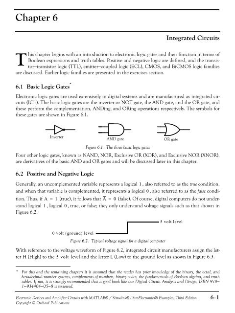
Chapter 6Integrated <strong>Circuits</strong>This chapter begins with an introduction to electronic logic gates <strong>and</strong> their function in terms ofBoolean expressions <strong>and</strong> truth tables. Positive <strong>and</strong> negative logic are defined, <strong>and</strong> the transistor−transistorlogic (TTL), emitter−coupled logic (ECL), CMOS, <strong>and</strong> BiCMOS logic familiesare discussed. Earlier logic families are presented in the exercises section.6.1 Basic Logic Gates *<strong>Electronic</strong> logic gates are used extensively in digital systems <strong>and</strong> are manufactured as integrated circuits(IC’s). The basic logic gates are the inverter or NOT gate, the AND gate, <strong>and</strong> the OR gate, <strong>and</strong>these perform the complementation, ANDing, <strong>and</strong> ORing operations respectively. The symbols forthese gates are shown in Figure 6.1.InverterFigure 6.1. The three basic logic gatesFour other logic gates, known as NAND, NOR, Exclusive OR (XOR), <strong>and</strong> Exclusive NOR (XNOR),are derivatives of the basic AND <strong>and</strong> OR gates <strong>and</strong> will be discussed later in this chapter.6.2 Positive <strong>and</strong> Negative LogicAND gateGenerally, an uncomplemented variable represents a logical 1 , also referred to as the true condition,<strong>and</strong> when that variable is complemented, it represents a logical 0 , also referred to as the false condition.Thus, if A = 1 (true), it follows that A = 0 (false). Of course, digital computers do not underst<strong>and</strong>logical 1 , logical 0 , true, or false; they only underst<strong>and</strong> voltage signals such as that shown inFigure 6.2.0 volt ( ground) levelFigure 6.2. Typical voltage signal for a digital computerOR gate5 volt levelWith reference to the voltage waveform of Figure 6.2, integrated circuit manufacturers assign the letterH (High) to the 5 volt level <strong>and</strong> the letter L (Low) to the ground level as shown in Figure 6.3.* For this <strong>and</strong> the remaining chapters it is assumed that the reader has prior knowledge of the binary, the octal, <strong>and</strong>hexadecimal number systems, complements of numbers, binary codes, the fundamentals of Boolean algebra, <strong>and</strong> truthtables. If not, it is strongly recommended that a good book like our Digital Circuit Analysis <strong>and</strong> Design, ISBN 978−1−934404−05−8 is reviewed.<strong>Electronic</strong> <strong>Devices</strong> <strong>and</strong> <strong>Amplifier</strong> <strong>Circuits</strong> with MATLAB® / Simulink® / Sim<strong>Electronic</strong>s® Examples, Third EditionCopyright © Orchard Publications6−1


