

Electronic Devices and Amplifier Circuits
Electronic Devices and Amplifier Circuits - Orchard Publications
Electronic Devices and Amplifier Circuits - Orchard Publications

You also want an ePaper? Increase the reach of your titles
YUMPU automatically turns print PDFs into web optimized ePapers that Google loves.
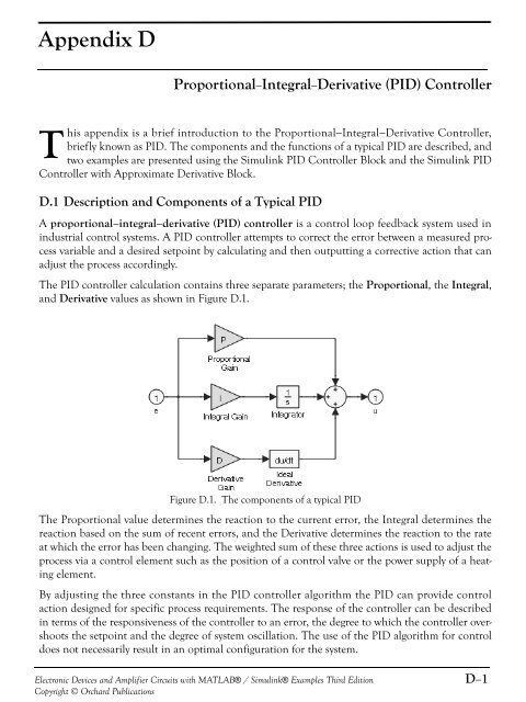
Appendix DProportional−Integral−Derivative (PID) ControllerThis appendix is a brief introduction to the Proportional−Integral−Derivative Controller,briefly known as PID. The components <strong>and</strong> the functions of a typical PID are described, <strong>and</strong>two examples are presented using the Simulink PID Controller Block <strong>and</strong> the Simulink PIDController with Approximate Derivative Block.D.1 Description <strong>and</strong> Components of a Typical PIDA proportional−integral−derivative (PID) controller is a control loop feedback system used inindustrial control systems. A PID controller attempts to correct the error between a measured processvariable <strong>and</strong> a desired setpoint by calculating <strong>and</strong> then outputting a corrective action that canadjust the process accordingly.The PID controller calculation contains three separate parameters; the Proportional, the Integral,<strong>and</strong> Derivative values as shown in Figure D.1.Figure D.1. The components of a typical PIDThe Proportional value determines the reaction to the current error, the Integral determines thereaction based on the sum of recent errors, <strong>and</strong> the Derivative determines the reaction to the rateat which the error has been changing. The weighted sum of these three actions is used to adjust theprocess via a control element such as the position of a control valve or the power supply of a heatingelement.By adjusting the three constants in the PID controller algorithm the PID can provide controlaction designed for specific process requirements. The response of the controller can be describedin terms of the responsiveness of the controller to an error, the degree to which the controller overshootsthe setpoint <strong>and</strong> the degree of system oscillation. The use of the PID algorithm for controldoes not necessarily result in an optimal configuration for the system.<strong>Electronic</strong> <strong>Devices</strong> <strong>and</strong> <strong>Amplifier</strong> <strong>Circuits</strong> with MATLAB® / Simulink® Examples Third EditionCopyright © Orchard PublicationsD−1


