USER’S MANUAL
Omron SX inverter manual
Omron SX inverter manual

Create successful ePaper yourself
Turn your PDF publications into a flip-book with our unique Google optimized e-Paper software.
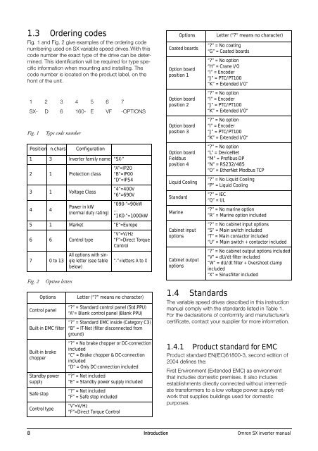
1.3 Ordering codes<br />
Fig. 1 and Fig. 2 give examples of the ordering code<br />
numbering used on SX variable speed drives. With this<br />
code number the exact type of the drive can be determined.<br />
This identification will be required for type specific<br />
information when mounting and installing. The<br />
code number is located on the product label, on the<br />
front of the unit.<br />
1 2 3 4 5 6 7<br />
SX- D 6 160- E VF -OPTIONS<br />
Fig. 1<br />
Fig. 2<br />
Type code number<br />
Position n.chars<br />
Option letters<br />
Configuration<br />
1 3 Inverter family name “SX-”<br />
2 1 Protection class<br />
3 1 Voltage Class<br />
4 4<br />
Power in kW<br />
(normal duty rating)<br />
“A”=IP20<br />
“B”=IP00<br />
“D”=IP54<br />
“4”=400V<br />
“6”=690V<br />
“090-”=90kW<br />
...<br />
“1K0-”=1000kW<br />
5 1 Market “E”=Europe<br />
6 6 Control type<br />
7 0 to 13<br />
Options<br />
Control panel<br />
Built-in EMC filter<br />
Built-in brake<br />
chopper<br />
Standby power<br />
supply<br />
Safe stop<br />
Control type<br />
All options with single<br />
letter (see table<br />
below)<br />
“V”=V/Hz<br />
“F”=Direct Torque<br />
Control<br />
“-”+letters A to X<br />
Letter (“?” means no character)<br />
“?” = Standard control panel (Std.PPU)<br />
“A”= Blank control panel (Blank PPU)<br />
“?” = Standard EMC inside (Category C3)<br />
“B” = IT-Net (filter disconnected from<br />
ground)<br />
“?” = No brake chopper or DC-connection<br />
included<br />
“C” = Brake chopper & DC-connection<br />
included<br />
“D” = Only DC-connection included<br />
“?” = Not included<br />
“E” = Standby power supply included<br />
“?” = Not included<br />
“F” = Safe stop included<br />
“V”=V/Hz<br />
“F”=Direct Torque Control<br />
Coated boards<br />
Option board<br />
position 1<br />
Option board<br />
position 2<br />
Option board<br />
position 3<br />
Option board<br />
Fieldbus<br />
position 4<br />
Liquid Cooling<br />
Standard<br />
Marine<br />
Options<br />
Cabinet input<br />
options<br />
Cabinet output<br />
options<br />
Letter (“?” means no character)<br />
“?” = No coating<br />
“G” = Coated boards<br />
“?” = No option<br />
“H” = Crane I/O<br />
“I” = Encoder<br />
“J” = PTC/PT100<br />
“K” = Extended I/O“<br />
“?” = No option<br />
“I” = Encoder<br />
“J” = PTC/PT100<br />
“K” = Extended I/O“<br />
“?” = No option<br />
“I” = Encoder<br />
“J” = PTC/PT100<br />
“K” = Extended I/O“<br />
“?” = No option<br />
“L” = DeviceNet<br />
“M” = Profibus-DP<br />
“N” = RS232/485<br />
“O” = EtherNet Modbus TCP<br />
“?” = No Liquid Cooling<br />
“P” = Liquid Cooling<br />
“?” = IEC<br />
“Q” = UL<br />
“?” = No marine option<br />
“R” = Marine option included<br />
“?” = No cabinet input options<br />
“S” = Main switch included<br />
“T” = Main contactor included<br />
“U” = Main switch + contactor included<br />
“?” = No cabinet output options included<br />
“V” = dU/dt filter included<br />
“W” = dU/dt filter + Overshoot clamp<br />
included<br />
“X” = Sinusfilter included<br />
1.4 Standards<br />
The variable speed drives described in this instruction<br />
manual comply with the standards listed in Table 1.<br />
For the declarations of conformity and manufacturer’s<br />
certificate, contact your supplier for more information.<br />
1.4.1 Product standard for EMC<br />
Product standard EN(IEC)61800-3, second edition of<br />
2004 defines the:<br />
First Environment (Extended EMC) as environment<br />
that includes domestic premises. It also includes<br />
establishments directly connected without intermediate<br />
transformers to a low voltage power supply network<br />
that supplies buildings used for domestic<br />
purposes.<br />
8 Introduction Omron SX inverter manual