USER’S MANUAL
Omron SX inverter manual
Omron SX inverter manual

Create successful ePaper yourself
Turn your PDF publications into a flip-book with our unique Google optimized e-Paper software.
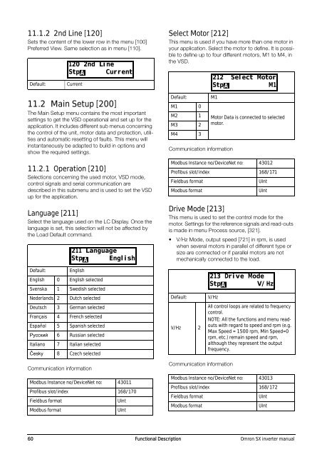
11.1.2 2nd Line [120]<br />
Sets the content of the lower row in the menu [100]<br />
Preferred View. Same selection as in menu [110].<br />
Default:<br />
Current<br />
11.2 Main Setup [200]<br />
The Main Setup menu contains the most important<br />
settings to get the VSD operational and set up for the<br />
application. It includes different sub menus concerning<br />
the control of the unit, motor data and protection, utilities<br />
and automatic resetting of faults. This menu will<br />
instantaneously be adapted to build in options and<br />
show the required settings.<br />
11.2.1 Operation [210]<br />
Selections concerning the used motor, VSD mode,<br />
control signals and serial communication are<br />
described in this submenu and is used to set the VSD<br />
up for the application.<br />
Language [211]<br />
Select the language used on the LC Display. Once the<br />
language is set, this selection will not be affected by<br />
the Load Default command.<br />
Default:<br />
English<br />
English 0 English selected<br />
Svenska 1 Swedish selected<br />
Nederlands 2<br />
Dutch selected<br />
Deutsch 3 German selected<br />
Français 4 French selected<br />
Español 5 Spanish selected<br />
Руccкий 6 Russian selected<br />
Italiano 7 Italian selected<br />
Česky 8 Czech selected<br />
Communication information<br />
Modbus Instance no/DeviceNet no: 43011<br />
Profibus slot/index 168/170<br />
Fieldbus format<br />
Modbus format<br />
120 2nd Line<br />
StpA<br />
Current<br />
211 Language<br />
Stp A English<br />
UInt<br />
UInt<br />
Select Motor [212]<br />
This menu is used if you have more than one motor in<br />
your application. Select the motor to define. It is possible<br />
to define up to four different motors, M1 to M4, in<br />
the VSD.<br />
Default:<br />
M1 0<br />
M2 1<br />
M3 2<br />
M4 3<br />
M1<br />
Communication information<br />
Drive Mode [213]<br />
This menu is used to set the control mode for the<br />
motor. Settings for the reference signals and read-outs<br />
is made in menu Process source, [321].<br />
• V/Hz Mode, output speed [721] in rpm, is used<br />
when several motors in parallel of different type or<br />
size are connected or if parallel motors are not<br />
mechanically connected to the load.<br />
Communication information<br />
Motor Data is connected to selected<br />
motor.<br />
Modbus Instance no/DeviceNet no: 43012<br />
Profibus slot/index 168/171<br />
Fieldbus format<br />
Modbus format<br />
Default:<br />
V/Hz 2<br />
V/Hz<br />
UInt<br />
UInt<br />
All control loops are related to frequency<br />
control.<br />
NOTE: All the functions and menu readouts<br />
with regard to speed and rpm (e.g.<br />
Max Speed = 1500 rpm, Min Speed=0<br />
rpm, etc.) remain speed and rpm,<br />
although they represent the output<br />
frequency.<br />
Modbus Instance no/DeviceNet no: 43013<br />
Profibus slot/index 168/172<br />
Fieldbus format<br />
Modbus format<br />
212 Select Motor<br />
StpA<br />
M1<br />
213 Drive Mode<br />
StpA<br />
V/Hz<br />
UInt<br />
UInt<br />
60 Functional Description Omron SX inverter manual