USER’S MANUAL
Omron SX inverter manual
Omron SX inverter manual

Create successful ePaper yourself
Turn your PDF publications into a flip-book with our unique Google optimized e-Paper software.
alarm<br />
messages.<br />
300 Process Appl<br />
StpA<br />
Fig. 37 Example 1st level menu<br />
220 Motor Data<br />
StpA<br />
Fig. 38 Example 2nd level menu<br />
221 Motor Volt<br />
Stp M1: 400V<br />
A<br />
Fig. 39 Example 3d level menu<br />
4161 Max Alarm<br />
Stp 0.1s<br />
A<br />
Table 16<br />
RUN<br />
(green)<br />
Motor shaft<br />
rotates<br />
Motor speed<br />
increase/<br />
decrease<br />
Motor<br />
stopped<br />
NOTE: If the control panel is built in, the back light of the<br />
display has the same function as the Power LED in Table<br />
16 (Blank panel LEDs).<br />
9.2.4 Control keys<br />
The control keys are used to give the Run, Stop or<br />
Reset commands directly. As default these keys are<br />
disabled, set for remote control. Activate the control<br />
keys by selecting Keyboard in the menus Ref Control<br />
[214] and Reset Ctrl [216].<br />
If the Enable function is programmed on one of the<br />
digital inputs, this input must be active to allow Run/<br />
Stop commands from the control panel.<br />
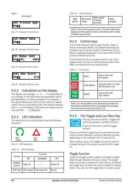
Table 17<br />
LED indication<br />
Control keys<br />
RUN L:<br />
gives a start with<br />
left rotation<br />
Fig. 40 Example 4th level menu<br />
9.2.2 Indications on the display<br />
The display can indicate +++ or - - - if a parameter is<br />
out of range. In the VSD there are parameters which<br />
are dependent on other parameters. For example, if<br />
the speed reference is 500 and the maximum speed<br />
value is set to a value below 500, this will be indicated<br />
with +++ on the display. If the minimum speed value is<br />
set over 500, - - - is displayed.<br />
9.2.3 LED indicators<br />
The symbols on the control panel have the following<br />
functions:<br />
Run<br />
Green<br />
Fig. 41 LED indications<br />
Table 16<br />
Symbol<br />
POWER<br />
(green)<br />
LED indication<br />
Trip<br />
Red<br />
Function<br />
Power<br />
Green<br />
ON BLINKING OFF<br />
Power on ---------------- Power off<br />
TRIP (red) VSD tripped Warning/Limit No trip<br />
STOP/RESET:<br />
RUN R:<br />
stops the motor or resets<br />
the VSD after a trip<br />
gives a start with<br />
right rotation<br />
NOTE: It is not possible to simultaneously activate the<br />
Run/Stop commands from the keyboard and remotely<br />
from the terminal strip (terminals 1-22).<br />
9.2.5 The Toggle and Loc/Rem Key<br />
This key has two functions: Toggle and<br />
switching between Loc/Rem function.<br />
Press one second to use the toggle<br />
function<br />
Press and hold the toggle key for more than five seconds<br />
to switch between Local and Remote function,<br />
depending on the settings in [2171] and [2172].<br />
When editing values, the toggle key can be used to<br />
change the sign of the value, see section 9.5, page<br />
51.<br />
Toggle function<br />
Using the toggle function makes it possible to easily<br />
step through selected menus in a loop. The toggle<br />
loop can contain a maximum of ten menus. As default<br />
the toggle loop contains the menus needed for Quick<br />
Setup. You can use the toggle loop to create a quick-<br />
48 Operation via the Control Panel Omron SX inverter manual