USER’S MANUAL
Omron SX inverter manual
Omron SX inverter manual

You also want an ePaper? Increase the reach of your titles
YUMPU automatically turns print PDFs into web optimized ePapers that Google loves.
When the "Safe Stop" condition is achieved by using<br />
these two different methods, which are independently<br />
controlled, this safety circuit ensures that the motor<br />
will not start running because:<br />
• The 24V DC signal is taken away from the "Inhibit"<br />
input, terminals 1 and 2, the safety relay K1 is<br />
switched off.<br />
The supply voltage to the driver circuits of the power conductors<br />
is switched off. This will inhibit the trigger pulses to<br />
the power conductors.<br />
• The trigger pulses from the control board are shut<br />
down.<br />
The Enable signal is monitored by the controller circuit<br />
which will forward the information to the PWM part on the<br />
Control board.<br />
To make sure that the safety relay K1 has been<br />
switched off, this should be guarded externally to<br />
ensure that this relay did not refuse to act. The Safe<br />
Stop option board offers a feedback signal for this via<br />
a second forced switched safety relay K2 which is<br />
switched on when a detection circuit has confirmed<br />
that the supply voltage to the driver circuits is shut<br />
down. See Table 33 for the contacts connections.<br />
To monitor the "Enable" function, the selection "RUN"<br />
on a digital output can be used. For setting a digital<br />
output, e.g. terminal 20 in the example Fig. 105,<br />
please refer to section 11.5.4, page 132 [540].<br />
When the "Inhibit" input is de-activated, the VSD display<br />
will show a blinking "SST" indication in section D<br />
(bottom left corner) and the red Trip LED on the Control<br />
panel will blink.<br />
To resume normal operation, the following steps have<br />
to be taken:<br />
• Release "Inhibit" input; 24V DC (High) to terminal 1<br />
and 2.<br />
• Give a STOP signal to the VSD, according to the<br />
set Run/Stop Control in menu [215].<br />
• Give a new Run command, according to the set<br />
Run/Stop Control in menu [215].<br />
NOTE: The method of generating a STOP command is<br />
dependent on the selections made in Start Signal Level/<br />
Edge [21A] and the use of a separate Stop input via<br />
digital input.<br />
WARNING: The safe stop function can never<br />
be used for electrical maintenance. For<br />
electrical maintenance the VSD should<br />
always be disconnected from the supply<br />
voltage.<br />
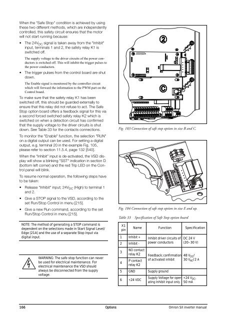
Fig. 103 Connection of safe stop option in size B and C.<br />
Fig. 104 Connection of safe stop option in size E and up.<br />
Table 33<br />
X1<br />
pin<br />
Specification of Safe Stop option board<br />
Name Function Specification<br />
1 Inhibit + Inhibit driver circuits of<br />
2 Inhibit - power conductors<br />
3<br />
4<br />
NO contact<br />
relay K2<br />
P contact<br />
relay K2<br />
Feedback; confirmation<br />
of activated inhibit<br />
5 GND Supply ground<br />
6 +24 VDC<br />
Supply Voltage for operating<br />
Inhibit input only.<br />
1<br />
2 3 4 5<br />
6<br />
6<br />
5<br />
4<br />
3<br />
2<br />
1<br />
DC 24 V<br />
(20–30 V)<br />
48 V DC /<br />
30 V AC /2 A<br />
+24 V DC ,<br />
50 mA<br />
166 Options Omron SX inverter manual