USER’S MANUAL
Omron SX inverter manual
Omron SX inverter manual

Create successful ePaper yourself
Turn your PDF publications into a flip-book with our unique Google optimized e-Paper software.
Communication information<br />
Modbus Instance no/DeviceNet no: 43541<br />
Profibus slot/index 170/190<br />
Fieldbus format<br />
Modbus format<br />
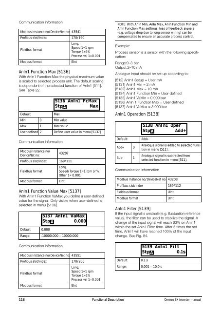
AnIn1 Function Max [5136]<br />
With AnIn1 Function Max the physical maximum value<br />
is scaled to selected process unit. The default scaling<br />
is dependent of the selected function of AnIn1 [511].<br />
See Table 22.<br />
Communication information<br />
Long,<br />
Speed 1=1 rpm<br />
Torque 1=1%<br />
Process val 1=0.001<br />
EInt<br />
Default:<br />
Max<br />
Min 0 Min value<br />
Max 1 Max value<br />
User-defined 2 Define user value in menu [5137]<br />
Modbus Instance no/<br />
DeviceNet no:<br />
43207<br />
Profibus slot/index 169/111<br />
Fieldbus format<br />
Modbus format<br />
Long,<br />
Speed/Torque 1=1 rpm or %.<br />
Other 1= 0.001<br />
EInt<br />
AnIn1 Function Value Max [5137]<br />
With AnIn1 Function VaMax you define a user-defined<br />
value for the signal. Only visible when user-defined is<br />
selected in menu [5136].<br />
Default: 0.000<br />
5136 AnIn1 FcMax<br />
Stp A<br />
Max<br />
5137 AnIn1 VaMax<br />
Stp 0.000<br />
A<br />
Range: -10000.000 – 10000.000<br />
NOTE: With AnIn Min, AnIn Max, AnIn Function Min and<br />
AnIn Function Max settings, loss of feedback signals<br />
(e.g. voltage drop due to long sensor wiring) can be<br />
compensated to ensure an accurate process control.<br />
Example:<br />
Process sensor is a sensor with the following specification:<br />
Range:0–3 bar<br />
Output:2–10 mA<br />
Analogue input should be set up according to:<br />
[512] AnIn1 Setup = User mA<br />
[5131] AnIn1 Min = 2 mA<br />
[5132] AnIn1 Max = 10 mA<br />
[5134] AnIn1 Function Min = User-defined<br />
[5135] AnIn1 VaMin = 0.000 bar<br />
[5136] AnIn 1 Function Max = User-defined<br />
[5137] AnIn1 VaMax = 3.000 bar<br />
AnIn1 Operation [5138]<br />
Default:<br />
Add+ 0<br />
Sub- 1<br />
Add+<br />
Communication information<br />
Analogue signal is added to selected function<br />
in menu [511].<br />
Analogue signal is subtracted from<br />
selected function in menu [511].<br />
Modbus Instance no/DeviceNet no: 43208<br />
Profibus slot/index 169/112<br />
Fieldbus format<br />
Modbus format<br />
5138 AnIn1 Oper<br />
Stp A Add+<br />
UInt<br />
UInt<br />
AnIn1 Filter [5139]<br />
If the input signal is unstable (e.g. fluctuation reference<br />
value), the filter can be used to stabilize the signal. A<br />
change of the input signal will reach 63% on AnIn1<br />
within the set AnIn1 Filter time. After 5 times the set<br />
time, AnIn1 will have reached 100% of the input<br />
change. See Fig. 84.<br />
Communication information<br />
Modbus Instance no/DeviceNet no: 43551<br />
Profibus slot/index 170/200<br />
Fieldbus format<br />
Modbus format<br />
Long,<br />
Speed 1=1 rpm<br />
Torque 1=1%<br />
Process val 1=0.001<br />
EInt<br />
Default:<br />
Range:<br />
5139 AnIn1 Filt<br />
Stp 0.1s<br />
A<br />
0.1 s<br />
0.001 – 10.0 s<br />
118 Functional Description Omron SX inverter manual