USER’S MANUAL
Omron SX inverter manual
Omron SX inverter manual

You also want an ePaper? Increase the reach of your titles
YUMPU automatically turns print PDFs into web optimized ePapers that Google loves.
Adding analogue inputs<br />
If more then one analogue input is set to the same<br />
function, the values of the inputs can be added<br />
together. In the following examples we assume that<br />
Process Source [321] is set to Speed.<br />
Example 1: Add signals with different weight (fine tuning).<br />
Signal on AnIn1 = 10 mA<br />
Signal on AnIn2 = 5 mA<br />
[511] AnIn1 Function = Process Ref.<br />
[512] AnIn1 Setup = 4-20 mA<br />
[5134] AnIn1 Function Min = Min (0 rpm)<br />
[5136] AnIn1 Function Max = Max (1500 rpm)<br />
[5138] AnIn1 Operation = Add+<br />
[514] AnIn2 Function = Process Ref.<br />
[515] AnIn2 Setup = 4-20 mA<br />
[5164] AnIn2 Function Min = Min (0 rpm)<br />
[5166] AnIn2 Function Max = User defined<br />
[5167] AnIn2 Value Max = 300 rpm<br />
[5168] AnIn2 Operation = Add+<br />
Calculation:<br />
AnIn1 = (10-4) / (20-4) x (1500-0) + 0 = 562.5 rpm<br />
AnIn2 = (5-4) / (20-4) x (300-0) + 0 = 18.75 rpm<br />
The actual process reference will be:<br />
+562.5 + 18.75 = 581 rpm<br />
Analogue Input Selection via Digital Inputs:<br />
When two different external Reference signals are<br />
used, e.g. 4-20mA signal from control centre and a 0-<br />
10 V locally mounted potentiometer, it is possible to<br />
switch between these two different analogue input signals<br />
via a Digital Input set to “AnIn Select”.<br />
AnIn1 is 4-20 mA<br />
AnIn2 is 0-10 V<br />
DigIn3 is controlling the AnIn selection; HIGH is 4-20<br />
mA, LOW is 0-10 V<br />
[511] AnIn1 Fc = Process Ref;<br />
set AnIn1 as reference signal input<br />
[512] AnIn1 Setup = 4-20mA;<br />
set AnIn1 for a current reference signal<br />
[513A] AnIn1 Enable = DigIn;<br />
set AnIn1 to be active when DigIn3 is HIGH<br />
[514] AnIn2 Fc = Process Ref;<br />
set AnIn2 as reference signal input<br />
[515] AnIn2 Setup = 0-10V;<br />
set AnIn2 for a voltage reference signal<br />
[516A] AnIn2 Enabl = !DigIn;<br />
set AnIn2 to be active when DigIn3 is LOW<br />
[523] DigIn3=AnIn;<br />
set DIgIn3 as input fot selection of AI reference<br />
Subtracting analogue inputs<br />
Example 2: Subtract two signals<br />
Signal on AnIn1 = 8 V<br />
Signal on AnIn2 = 4 V<br />
[511] AnIn1 Function = Process Ref.<br />
[512] AnIn1 Setup = 0-10 V<br />
[5134] AnIn1 Function Min = Min (0 rpm)<br />
[5136] AnIn1 Function Max = Max (1500 rpm)<br />
[5138] AnIn1 Operation = Add+<br />
[514] AnIn2 Function = Process Ref.<br />
[515] AnIn2 Setup = 0-10 V<br />
[5164] AnIn2 Function Min = Min (0 rpm)<br />
[5166] AnIn2 Function Max = Max (1500 rpm)<br />
[5168] AnIn2 Operation = Sub-<br />
Calculation:<br />
AnIn1 = (8-0) / (10-0) x (1500-0) + 0 = 1200 rpm<br />
AnIn2 = (4-0) / (10-0) x (1500-0) + 0 = 600 rpm<br />
The actual process reference will be:<br />
+1200 - 600 = 600 rpm<br />
AnIn1 Setup [512]<br />
The analogue input setup is used to configure the analogue<br />
input in accordance with the signal used that will<br />
be connected to the analogue input. With this selection<br />
the input can be determined as current (4-20 mA)<br />
or voltage<br />
(0-10 V) controlled input. Other selections are available<br />
for using a threshold (live zero), a bipolar input function,<br />
or a user defined input range. With a bipolar input<br />
reference signal, it is possible to control the motor in<br />
two directions. See Fig. 80.<br />
NOTE: The selection of voltage or current input is done<br />
with S1. When the switch is in voltage mode only the<br />
voltage menu items are selectable. With the switch in<br />
current mode only the current menu items are<br />
selectable.<br />
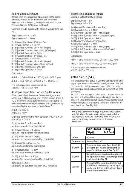
Default:<br />
Dependent on<br />
4–20mA 0<br />
0–20mA 1<br />
User mA 2<br />
512 AnIn1 Setup<br />
Stp A 4-20mA<br />
4-20 mA<br />
Setting of switch S1<br />
The current input has a fixed threshold<br />
(Live Zero) of 4 mA and controls the full<br />
range for the input signal. See Fig. 82.<br />
Normal full current scale configuration of<br />
the input that controls the full range for the<br />
input signal. See Fig. 81.<br />
The scale of the current controlled input,<br />
that controls the full range for the input signal.<br />
Can be defined by the advanced AnIn<br />
Min and AnIn Max menus.<br />
Omron SX inverter manual Functional Description 115