USER’S MANUAL
Omron SX inverter manual
Omron SX inverter manual

Create successful ePaper yourself
Turn your PDF publications into a flip-book with our unique Google optimized e-Paper software.
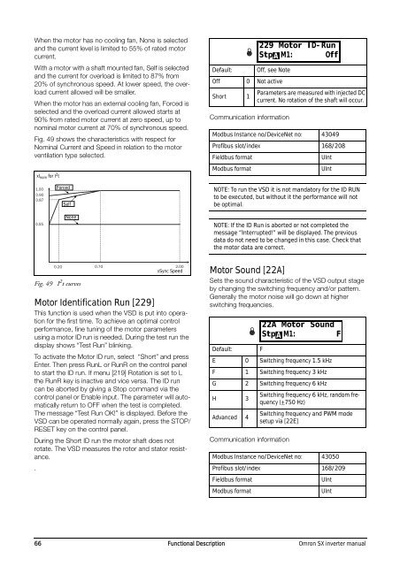
When the motor has no cooling fan, None is selected<br />
and the current level is limited to 55% of rated motor<br />
current.<br />
With a motor with a shaft mounted fan, Self is selected<br />
and the current for overload is limited to 87% from<br />
20% of synchronous speed. At lower speed, the overload<br />
current allowed will be smaller.<br />
When the motor has an external cooling fan, Forced is<br />
selected and the overload current allowed starts at<br />
90% from rated motor current at zero speed, up to<br />
nominal motor current at 70% of synchronous speed.<br />
Fig. 49 shows the characteristics with respect for<br />
Nominal Current and Speed in relation to the motor<br />
ventilation type selected.<br />
xI nom for I 2 t<br />
Default:<br />
<br />
Off, see Note<br />
Off 0 Not active<br />
Short 1<br />
Communication information<br />
Parameters are measured with injected DC<br />
current. No rotation of the shaft will occur.<br />
Modbus Instance no/DeviceNet no: 43049<br />
Profibus slot/index 168/208<br />
Fieldbus format<br />
Modbus format<br />
229 Motor ID-Run<br />
Stp M1: Off<br />
A<br />
UInt<br />
UInt<br />
1.00<br />
0.90<br />
0.87<br />
0.55<br />
Forced<br />
Self<br />
None<br />
NOTE: To run the VSD it is not mandatory for the ID RUN<br />
to be executed, but without it the performance will not<br />
be optimal.<br />
NOTE: If the ID Run is aborted or not completed the<br />
message “Interrupted!” will be displayed. The previous<br />
data do not need to be changed in this case. Check that<br />
the motor data are correct.<br />
0.20 0.70 2.00<br />
xSync Speed<br />
Fig. 49 I 2 t curves<br />
Motor Identification Run [229]<br />
This function is used when the VSD is put into operation<br />
for the first time. To achieve an optimal control<br />
performance, fine tuning of the motor parameters<br />
using a motor ID run is needed. During the test run the<br />
display shows “Test Run” blinking.<br />
To activate the Motor ID run, select “Short” and press<br />
Enter. Then press RunL or RunR on the control panel<br />
to start the ID run. If menu [219] Rotation is set to L<br />
the RunR key is inactive and vice versa. The ID run<br />
can be aborted by giving a Stop command via the<br />
control panel or Enable input. The parameter will automatically<br />
return to OFF when the test is completed.<br />
The message “Test Run OK!” is displayed. Before the<br />
VSD can be operated normally again, press the STOP/<br />
RESET key on the control panel.<br />
During the Short ID run the motor shaft does not<br />
rotate. The VSD measures the rotor and stator resistance.<br />
.<br />
Motor Sound [22A]<br />
Sets the sound characteristic of the VSD output stage<br />
by changing the switching frequency and/or pattern.<br />
Generally the motor noise will go down at higher<br />
switching frequencies.<br />
Default:<br />
Communication information<br />
F<br />
E 0 Switching frequency 1.5 kHz<br />
F 1 Switching frequency 3 kHz<br />
G 2 Switching frequency 6 kHz<br />
H 3<br />
Advanced 4<br />
Switching frequency 6 kHz, random frequency<br />
(+750 Hz)<br />
Switching frequency and PWM mode<br />
setup via [22E]<br />
Modbus Instance no/DeviceNet no: 43050<br />
Profibus slot/index 168/209<br />
Fieldbus format<br />
Modbus format<br />
<br />
22A Motor Sound<br />
Stp M1: F<br />
A<br />
UInt<br />
UInt<br />
66 Functional Description Omron SX inverter manual