USER’S MANUAL
Omron SX inverter manual
Omron SX inverter manual

Create successful ePaper yourself
Turn your PDF publications into a flip-book with our unique Google optimized e-Paper software.
Virtual Connection 1 Source [562]<br />
With this function the source of the virtual connection<br />
is defined. See DigOut 1 for description of the different<br />
selections.<br />
Default:<br />
Off<br />
Selection: Same as for menu [541].<br />
Communication information<br />
Modbus Instance no/DeviceNet no: 43282<br />
Profibus slot/index 169/186<br />
Fieldbus format<br />
Modbus format<br />
UInt<br />
UInt<br />
Virtual Connections 2-8 [563] to [56G]<br />
Same function as virtual connection 1 [561] and [562].<br />
Communication information for virtual connections 2-8<br />
Destination.<br />
Modbus Instance no/DeviceNet no:<br />
Profibus slot/index<br />
Fieldbus format<br />
Modbus format<br />
43283, 43285, 43287,<br />
43289, 43291, 43293,<br />
43295<br />
169/ 187, 189, 191,<br />
193, 195, 197, 199<br />
UInt<br />
UInt<br />
Communication information for virtual connections 2-8<br />
Source.<br />
Modbus Instance no/DeviceNet no:<br />
Profibus slot/index<br />
Fieldbus format<br />
Modbus format<br />
562 VIO 1 Source<br />
Stp A<br />
Off<br />
43284, 43286, 43288,<br />
43290, 43292, 43294,<br />
43296<br />
169/ 188, 190, 192,<br />
194, 196, 198, 200<br />
UInt<br />
UInt<br />
11.6 Logical Functions and<br />
Timers [600]<br />
With the Comparators, Logic Functions and Timers,<br />
conditional signals can be programmed for control or<br />
signalling features. This gives you the ability to compare<br />
different signals and values in order to generate<br />
monitoring/controlling features.<br />
11.6.1 Comparators [610]<br />
The comparators available make it possible to monitor<br />
different internal signals and values, and visualize via<br />
digital output or a contact, when a specific value or<br />
status is reached or established.<br />
There are 2 analogue comparators that compare any<br />
available analogue value (including the analogue reference<br />
inputs) with two adjustable constants.<br />
For the two analogue comparators two different constants<br />
are available, Level HI and Level LO. With these<br />
two levels, it is possible to create a clear hysteresis for<br />
the analogue comparator between setting and resetting<br />
the comparator output. This function gives a clear<br />
difference in switching levels, which lets the process<br />
adapt until a certain action is started. With such a hysteresis,<br />
even an instable analogue signal can be monitored<br />
without getting a nervous comparator signal.<br />
Another function is to get a clear indication that a certain<br />
situation has occurred; the comparator can latch<br />
by set Level LO to a higher value than Level HI.<br />
There are 2 digital comparators that compare any<br />
available digital signal.<br />
The output signals of these comparators can be logically<br />
tied together to yield a logical output signal.<br />
All the output signals can be programmed to the digital<br />
or relay outputs or used as a source for the virtual<br />
connections [560].<br />
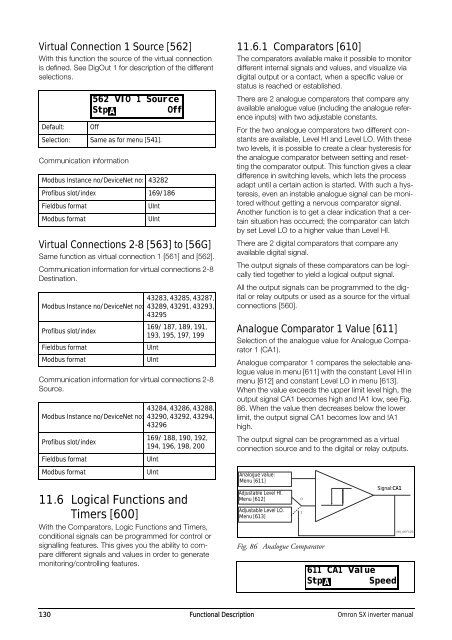
Analogue Comparator 1 Value [611]<br />
Selection of the analogue value for Analogue Comparator<br />
1 (CA1).<br />
Analogue comparator 1 compares the selectable analogue<br />
value in menu [611] with the constant Level HI in<br />
menu [612] and constant Level LO in menu [613].<br />
When the value exceeds the upper limit level high, the<br />
output signal CA1 becomes high and !A1 low, see Fig.<br />
86. When the value then decreases below the lower<br />
limit, the output signal CA1 becomes low and !A1<br />
high.<br />
The output signal can be programmed as a virtual<br />
connection source and to the digital or relay outputs.<br />
Analogue value:<br />
Menu [611]<br />
Adjustable Level HI.<br />
Menu [612]<br />
Adjustable Level LO.<br />
Menu [613]<br />
Fig. 86 Analogue Comparator<br />
0<br />
1<br />
Signal:CA1<br />
611 CA1 Value<br />
Stp A Speed<br />
(NG_06-F125)<br />
130 Functional Description Omron SX inverter manual