MDrive 23 Plus2 EtherNet/IP - Koco Motion GmbH
MDrive 23 Plus2 EtherNet/IP - Koco Motion GmbH
MDrive 23 Plus2 EtherNet/IP - Koco Motion GmbH

You also want an ePaper? Increase the reach of your titles
YUMPU automatically turns print PDFs into web optimized ePapers that Google loves.
V1.000, 10.2011<br />
<strong>MDrive</strong>Plus <strong>EtherNet</strong>/<strong>IP</strong> 6 Installation<br />
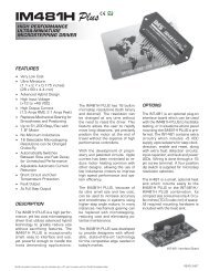
6.3.3 Connection of the I/O interface<br />
Integrated <strong>Motion</strong> System<br />
Pin assignments<br />
Motor<br />
Shaft<br />
P1<br />
14 12 10 8 6 4 2<br />
13 11 9 7 5 3 1<br />
P2<br />
Top-Rear view<br />
Motor<br />
Shaft<br />
Side view<br />
1<br />
2<br />
3<br />
4<br />
5<br />
6<br />
7<br />
8<br />
Figure 6.4: I/O interface pin assignments<br />
Pin Signal Function Cable option wire color Twisted Pair #<br />
1 IO POWER +24 VDC input for sourcing outputs Red 1<br />
2 AUX POWER 12 to 24 VDC Auxiliary supply voltage Black<br />
3 IO1 General purpose I/O point #1 Orange 2<br />
4 IO2 General purpose I/O point #2 Black<br />
5 IO3 General purpose I/O point #3 Brown 3<br />
6 IO4 General purpose I/O point #4 Black<br />
71) N/C Not connected Yellow 4<br />
81) Black<br />
91) Blue 5<br />
101) Black<br />
11 CAPT/TR<strong>IP</strong> Capture input/ trip output point Green 6<br />
12 ANALOG IN Analog input Black<br />
13 STEP IO Step clock/CH A/Up (CW) White 7<br />
14 DIR IO Direction/CH B/Down (CCW) Black<br />
P3<br />
1) Pins in the gray shaded area are not connected, if using the cable option these<br />
may be left floating.<br />
1<br />
2<br />
43