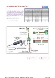
MDrive 23 Plus2 EtherNet/IP - Koco Motion GmbH
MDrive 23 Plus2 EtherNet/IP - Koco Motion GmbH
MDrive 23 Plus2 EtherNet/IP - Koco Motion GmbH

You also want an ePaper? Increase the reach of your titles
YUMPU automatically turns print PDFs into web optimized ePapers that Google loves.
V1.000, 10.2011<br />
<strong>MDrive</strong>Plus <strong>EtherNet</strong>/<strong>IP</strong> 12 Glossary<br />
Integrated <strong>Motion</strong> System<br />
Opto-Isolated A method of sending a signal from one piece of equipment to another<br />
without the usual requirement of common ground potentials. The signal<br />
is transmitted optically with a light source (usually a Light Emitting<br />
Diode) and a light sensor (usually a photo-sensitive transistor). These<br />
optical components provide electrical isolation.<br />
Parameter Device data and values that can be set by the user.<br />
Persistent Indicates whether the value of the parameter remains in the memory<br />
after the device is switched off.<br />
PLC Programmable logic controller<br />
Position lead/lag The HMT circuitry continually tracks the position lead or lag error, and<br />
may use it to correct position.<br />
Position make-up When active, the position make-up can correct for position errors occurring<br />
due to transient loads. The lost steps may be interleaved with<br />
incoming steps, or reinserted into the profile at the end of a move.<br />
Power stage The power stage controls the motor. The power stage generates currents<br />
for controlling the motor on the basis of the positioning signals<br />
from the controller.<br />
Pull-In Torque This is the maximum torque the stepper motor can develop when instantaneously<br />
started at that speed.<br />
Pull-Out Torque This is the maximum torque that the stepper can develop once an acceleration<br />
profile has been used to “ramp” it to the target speed.<br />
Quick Stop Function used to enable fast deceleration of the motor via a command<br />
or in the event of a malfunction.<br />
Resolution The smallest positioning increment that can be achieved.<br />
Resonance The frequency that a stepper motor system may begin to oscillate. Primary<br />
resonance frequency occurs at about one revolution per second.<br />
This oscillation will cause a loss of effective torque and may result in<br />
loss of synchronism. The designer should consider reducing or shifting<br />
the resonance frequency by utilizing half step or micro-step techniques<br />
or work outside the primary resonance frequency.<br />
Rotor The moving part of the motor, consisting of the shaft and the magnets.<br />
These magnets are similar to the field winding of a brush type DC motor<br />
71