

VGB POWERTECH 7 (2021) - International Journal for Generation and Storage of Electricity and Heat
VGB PowerTech - International Journal for Generation and Storage of Electricity and Heat. Issue 7 (2021). Technical Journal of the VGB PowerTech Association. Energy is us! Optimisation of power plants. Thermal waste utilisation.
VGB PowerTech - International Journal for Generation and Storage of Electricity and Heat. Issue 7 (2021).
Technical Journal of the VGB PowerTech Association. Energy is us!
Optimisation of power plants. Thermal waste utilisation.
- No tags were found...

Create successful ePaper yourself
Turn your PDF publications into a flip-book with our unique Google optimized e-Paper software.
<strong>VGB</strong> PowerTech 7 l <strong>2021</strong><br />
Study on the integrity <strong>of</strong> containment against hydrogen threats<br />
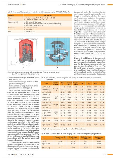
Tab. 4. Summary <strong>of</strong> the containment model <strong>for</strong> the 3D analysis using the GASFLOW-MPI code.<br />
Elements<br />
Specifications<br />
Mesh Number <strong>of</strong> cells : 71(X)×71(Y) × 81(Z) = 408,321<br />
Cell size: 59.2cm×59.2cm ×90.7 cm<br />
Passive heat sink<br />
Components<br />
PAR<br />
A<br />
Slab model: CAD structure<br />
Wall model: Steel shell containment, concrete shield building<br />
Sink model: Internal structures<br />
Containment spray<br />
Fan cooler<br />
NUKEM model<br />
Fig. 4. Containment model <strong>of</strong> the reference plant: (a) Containment mesh model,<br />
(b) PAR arrangement in the containment.<br />
B<br />
in each cell under the condition that the<br />
combustion model is activated. In addition,<br />
it is possible to calculate the <strong>for</strong>ced<br />
combustion using an ignitor. Spontaneous<br />
ignition spreads very quickly, while the<br />
combustion using an ignitor takes longer<br />
than spontaneous ignition until the flame<br />
starts at one location <strong>and</strong> burns all the hydrogen<br />
in the containment. There<strong>for</strong>e, in<br />
this study, both conditions can be applied<br />
to produce conservative combustion loads<br />
from the viewpoint <strong>of</strong> the structural analysis<br />
<strong>of</strong> the integrity <strong>of</strong> the containment; this<br />
ensures that the combustion is more active<br />
<strong>and</strong> occurs in a short time. The A1, A2, <strong>and</strong><br />
A5 cases result in thermodynamic <strong>and</strong> gas<br />
composition conditions in which combustion<br />
cannot occur. In addition, the A7 case<br />
showed no hydrogen release at the highest<br />
containment pressure. There<strong>for</strong>e, the<br />
combustion load analysis was per<strong>for</strong>med<br />
in eight cases, except <strong>for</strong> A1, A2, A5, <strong>and</strong><br />
A7.<br />
F i g u r e 5 <strong>and</strong> F i g u r e 6 show the typical<br />
hydrogen concentration <strong>and</strong> containment<br />
pressure distribution during combustion<br />
<strong>for</strong> the B3 case, respectively, <strong>for</strong> the<br />
analysis cases described in Ta b l e 6 . The<br />
B3 case is a case in which a very conservative<br />
condition with a very high hydrogen<br />
concentration is applied as a result <strong>of</strong> the<br />
combustion analysis assuming that there is<br />
––<br />
Compartment average maximum pressure<br />
timing (AP)<br />
––<br />
Compartment average maximum temperature<br />
timing (AT)<br />
––<br />
Compartment average maximum hydrogen<br />
concentration timing (AH)<br />
Ta b l e 5 shows the conditions <strong>of</strong> all the<br />
cases <strong>for</strong> the combustion load analysis. A<br />
total <strong>of</strong> 12 cases were selected by applying<br />
three combustion condition points to four<br />
severe accident scenarios. For the MLOCA<br />
case, the maximum pressure condition<br />
(A7) was not considered in the analysis because<br />
there was no hydrogen discharge until<br />
the point <strong>of</strong> reaching the maximum<br />
pressure. The conservative analysis conditions<br />
were also derived. The B1 case applies<br />
the regulatory requirement <strong>for</strong> the<br />
average hydrogen concentration in the<br />
containment: 10 vol. % <strong>of</strong> the average hydrogen<br />
concentration. The B2 case is reflected<br />
in the maximum hydrogen concentration<br />
value identified in the LOOP case<br />
analysis using MAAP5 as the initial condition<br />
<strong>of</strong> the entire containment. The B3 case<br />
is the condition at the point where the<br />
maximum average hydrogen concentration<br />
in the containment is shown just be<strong>for</strong>e the<br />
reactor vessel failure, assuming that PARs<br />
do not work in the event <strong>of</strong> a SLOCA, which<br />
is associated with the highest amount <strong>of</strong><br />
hydrogen discharge.<br />
The GASFLOW-MPI code whether or not<br />
spontaneous ignition is possible based on<br />
the Shapiro diagram considering <strong>of</strong> the hydrogen,<br />
oxygen, <strong>and</strong> steam concentrations<br />
Tab. 5. Test matrix <strong>for</strong> pressure analysis due to hydrogen combustion under severe accident<br />
conditions.<br />
Case<br />
Accident<br />
Scenario<br />
Time<br />
[s]<br />
Pressure<br />
[kPa]<br />
Temperature<br />
[K]<br />
H 2 O 2 H 2 O N 2<br />
A1(LW-WP-AP)<br />
44,046 210.8 398 0.024 0.070 0.491 0.416<br />
A2(LW-WP-AT)<br />
LOCCW<br />
(LW)<br />
45,950 210.5 398 0.022 0.068 0.494 0.416<br />
A3(LW-WP-AH) 32,124 183.3 461 0.059 0.106 0.417 0.583<br />
A4(LP-WP-AP)<br />
20,820 259.3 413 0.042 0.071 0.559 0.328<br />
A5(LP-WP-AT)<br />
LOOP<br />
(LP)<br />
20,720 234.0 438 0.035 0.039 0.728 0.198<br />
A6(LP-WP-AH) 24,222 193.6 478 0.059 0.081 0.444 0.417<br />
A7(MC-WP-AP)<br />
4,805 261.9 391 0.000 0.084 0.578 0.338<br />
A8(MC-WP-AT)<br />
MLOCA<br />
(ML)<br />
33,524 175.6 392 0.065 0.108 0.347 0.481<br />
A9(MC-WP-AH) 33,424 154.2 375 0.065 0.106 0.354 0.476<br />
A10(SC-WP-AP)<br />
26,918 173.9 380 0.061 0.109 0.332 0.498<br />
A11(SC-WP-AT)<br />
SLOCA<br />
(SL)<br />
26,418 171.8 382 0.060 0.112 0.325 0.503<br />
A12(SC-WP-AH) 28,718 156.0 415 0.072 0.109 0.277 0.541<br />
B1(LMT) Limited - 150.0 400 0.100 0.168 0.100 0.632<br />
B2(LP-WP-MH) LOOP 20,720 234.0 438 0.125 0.039 0.728 0.108<br />
B3(SC-WOP-AH)<br />
SLOCA<br />
W/O<br />
PAR*<br />
30,020 159.9 360 0.123 0.130 0.230 0.518<br />
* W/O PAR: Severe accident analysis per<strong>for</strong>med without PAR consideration.<br />
Tab. 6. Analysis results <strong>of</strong> the structural integrity <strong>of</strong> the containment against hydrogen threats.<br />
Case<br />
Membrane strain<br />
[%]<br />
Plastic strain<br />
[%]<br />
Equivalent stress<br />
[MPa]<br />
Displacement<br />
[mm]<br />
B1(LMT) 0.278 0.216 262.99 39.65<br />
B2(LP-WP-MH) 0.447 0.366 265.17 43.94<br />
B3<br />
(SC-WOP-AH)<br />
1.319 1.334 278.82 81.54<br />
73


