

VGB POWERTECH 7 (2021) - International Journal for Generation and Storage of Electricity and Heat
VGB PowerTech - International Journal for Generation and Storage of Electricity and Heat. Issue 7 (2021). Technical Journal of the VGB PowerTech Association. Energy is us! Optimisation of power plants. Thermal waste utilisation.
VGB PowerTech - International Journal for Generation and Storage of Electricity and Heat. Issue 7 (2021).
Technical Journal of the VGB PowerTech Association. Energy is us!
Optimisation of power plants. Thermal waste utilisation.
- No tags were found...

You also want an ePaper? Increase the reach of your titles
YUMPU automatically turns print PDFs into web optimized ePapers that Google loves.
<strong>VGB</strong> PowerTech 7 l <strong>2021</strong><br />
Verification <strong>of</strong> SPACE code based on an MSGTR experiment at the ATLAS-PAFS facility<br />
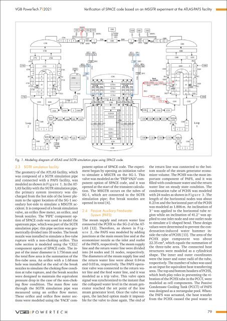
Fig. 1. Modeling diagram <strong>of</strong> ATLAS <strong>and</strong> SGTR simulation pipe using SPACE code.<br />
2.3 SGTR simulation facility<br />
The geometry <strong>of</strong> the ATLAS facility, which<br />
was composed <strong>of</strong> a SGTR simulation pipe<br />
<strong>and</strong> connected with a PAFS facility, was<br />
modeled as shown in F i g u r e 1. In the AT-<br />
LAS facility with the SGTR simulation pipe,<br />
the primary system inventory was discharged<br />
from the hot side <strong>of</strong> the lower plenum<br />
to the upper location <strong>of</strong> the SG-1 secondary<br />
hot-side to simulate a MSGTR accident.<br />
It is composed <strong>of</strong> a break simulation<br />
valve, an orifice flow meter, an orifice, <strong>and</strong><br />
break nozzles. The ‘PIPE’ component option<br />
<strong>of</strong> SPACE code was used to model the<br />
upstream pipe, which was part <strong>of</strong> the SGTR<br />
simulation pipe; this pipe section was geometrically<br />
divided into 10 nodes. The break<br />
nozzle was installed to simulate a five-tube<br />
rupture with a non-choking orifice. This<br />
tube section is modeled using the ‘CELL’<br />
component option <strong>of</strong> SPACE code. The input<br />
<strong>of</strong> the inner diameter is 1.756 mm <strong>and</strong><br />
the total flow area is the summation <strong>of</strong> the<br />
five-tube area. An orifice with a 1.68 mm<br />
hole was installed at the end <strong>of</strong> the break<br />
nozzles to simulate the choking flow condition<br />
at tube rupture, <strong>and</strong> the break nozzles<br />
were designed to maintain the equivalent<br />
pressure drop in the case <strong>of</strong> the non-choking<br />
flow condition. The mass flow rate<br />
through the SGTR simulation pipe was<br />
measured using an orifice flow meter.<br />
These orifice <strong>and</strong> orifice flow meter sections<br />
were modeled using the ‘FACE’ component<br />
option <strong>of</strong> SPACE code. The experiment<br />
began by opening an initiation valve<br />
to simulate a MSGTR on the SG-1. This<br />
valve was modeled as the ‘TRIP VALV’ component<br />
option <strong>of</strong> SPACE code, <strong>and</strong> it was<br />
opened at the start <strong>of</strong> the transient calculation.<br />
The MSGTR occurs on the tubes <strong>of</strong><br />
SG-1, which are connected to the SGTR<br />
simulation pipe; five break nozzles are<br />
opened in total [4].<br />
2.4 Passive Auxiliary Feedwater<br />
System (PAFS)<br />
The steam supply <strong>and</strong> return water line<br />
connected the PCHX to the SG-2 <strong>of</strong> the AT-<br />
LAS [12]. There<strong>for</strong>e, as shown in F i g -<br />
u r e 2 , the PAFS was modeled by adding<br />
junctions at the main steam line <strong>and</strong> at the<br />
economizer nozzle as the inlet <strong>and</strong> outlet<br />
<strong>of</strong> the PAFS, respectively. The steam supply<br />
line <strong>and</strong> the return water line were divided<br />
into 24 nodes <strong>and</strong> 31 nodes, respectively.<br />
The diameters <strong>of</strong> the steam supply line <strong>and</strong><br />
the return water line were about 0.04 m<br />
<strong>and</strong> 0.03 m, respectively. The PAFS operation<br />
valve was connected to the return water<br />
line <strong>and</strong> the feed water line, <strong>and</strong> it was<br />
modeled as a trip valve. This valve open<br />
signal was synchronized to the instant that<br />
the collapsed water level in the steam generator<br />
reached the set point <strong>of</strong> the low<br />
steam generator level. Once the valve was<br />
open, the latched option made it impossible<br />
<strong>for</strong> the valve to close again. The end <strong>of</strong><br />
the return line was connected to the bottom<br />
nozzle <strong>of</strong> the steam generator economizer<br />
volume. The PCHX was the most important<br />
component <strong>of</strong> PAFS, <strong>and</strong> it was<br />
filled with condensate water <strong>and</strong> the return<br />
water line on steady state condition. The<br />
condensation tube <strong>of</strong> PCHX was modeled<br />
with 24 nodes as shown in F i g u r e 3 . The<br />
length <strong>of</strong> the horizontal nodes was about<br />
0.23 m <strong>and</strong> the horizontal part <strong>of</strong> the PCHX<br />
was modeled as 1.806 m. An inclination <strong>of</strong><br />
3 ° was applied to the horizontal tube region<br />
while an inclination <strong>of</strong> 41.2 ° was applied<br />
to one inlet node <strong>and</strong> one outlet node<br />
to simulate a U-shaped bend. These design<br />
values were determined to prevent the condensation-induced<br />
water hammer inside<br />
the tube <strong>of</strong> PCHX [13]. The area <strong>of</strong> the<br />
PCHX pipe component was about<br />
22.35 cm 2 , which equals the summation <strong>of</strong><br />
the three-tube area. The connected heat<br />
structures were modeled as a cylindrical<br />
shape. The inner <strong>and</strong> outer coordinates<br />
were the inner <strong>and</strong> outer radii <strong>of</strong> the tube,<br />
respectively. The number <strong>of</strong> tubes was used<br />
as an input <strong>for</strong> equivalent heat transferring<br />
area. The top <strong>and</strong> bottom headers <strong>of</strong> PCHX,<br />
which both play roles in preventing the vibration<br />
<strong>of</strong> the PCHX tube in the PCCT, were<br />
modeled as cell components. The Passive<br />
Condensate Cooling Tank (PCCT) <strong>of</strong> PAFS<br />
was designed as a rectangular pool. Whenthe<br />
PAFS was actuated, the heat transfer<br />
from the PCHX caused the pool water in<br />
79


