Old School Chopper Frame Fabrication - Knucklebuster
Old School Chopper Frame Fabrication - Knucklebuster
Old School Chopper Frame Fabrication - Knucklebuster

Create successful ePaper yourself
Turn your PDF publications into a flip-book with our unique Google optimized e-Paper software.
Figure 1<br />
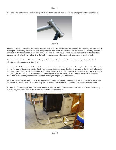
In Figure 2 we see the more common design where the down tubes are welded onto the lower portion of the steering neck.<br />
Figure 2<br />
People will argue all day about the various pros and cons of either type of design but basically the reasoning goes that the old<br />
design puts less bending stress on the neck tube proper. In other words the tube itself is not subjected to a bending load and<br />
isn't really a structural member of the main frame. The more modern design actually makes the neck tube a structural frame<br />
member and when loads are applied from the backbone or the down tubes the neck is subjected to a bending load.<br />
When one considers the wall thickness of the typical steering neck I doubt whether either design type has a structural<br />
advantage or disadvantage over the other.<br />
I personally think that its easier to fabricate the type of connections shown in Figure 2 but having built frames the old way for<br />
so long I'm kind of stuck in my habits. One big advantage of building frames the old way however is that the neck rake angle<br />
can be very easily changed without messing with the down tubes. This is a very practical feature as it allows you to re-chop a<br />
<strong>Chopper</strong> if you want to change its appearance or handling characteristics later on. Additionally it is easier to straighten a<br />
frame built with the old style of neck connection if it ever gets banged up in an accident.<br />
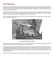
All of the plans, diagrams and photos of our projects are intended to be fabricated using what we've called the old-style neck<br />
connection. If you opt to build it the other way you will have to make changes in the down tube angles and dimensions.<br />
In part four of this series we bent the forward portion of the lower rails that created the down tube section and now we've got<br />
to create the joint where the two down tubes connect at their uppermost end.<br />
Figure 3