Old School Chopper Frame Fabrication - Knucklebuster
Old School Chopper Frame Fabrication - Knucklebuster
Old School Chopper Frame Fabrication - Knucklebuster

You also want an ePaper? Increase the reach of your titles
YUMPU automatically turns print PDFs into web optimized ePapers that Google loves.
Once the pattern is cut it can be used as a template to scribe around on the 3/8" cold-rolled stock used to fabricate the adjuster<br />
plates or it can be used to make a wooden 'follow' block if you're going to plasma or flame cut the material. We prefer doing<br />
this type of work on a Band saw so we simply transferred the pattern directly to the steel.<br />
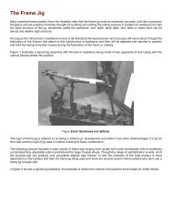
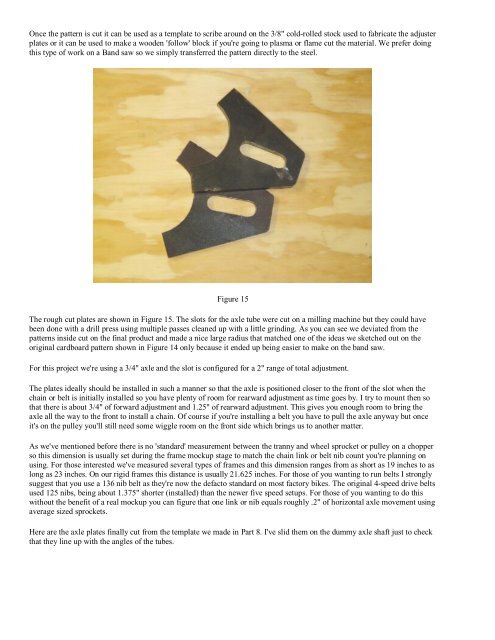
Figure 15<br />
The rough cut plates are shown in Figure 15. The slots for the axle tube were cut on a milling machine but they could have<br />
been done with a drill press using multiple passes cleaned up with a little grinding. As you can see we deviated from the<br />
patterns inside cut on the final product and made a nice large radius that matched one of the ideas we sketched out on the<br />
original cardboard pattern shown in Figure 14 only because it ended up being easier to make on the band saw.<br />
For this project we're using a 3/4" axle and the slot is configured for a 2" range of total adjustment.<br />
The plates ideally should be installed in such a manner so that the axle is positioned closer to the front of the slot when the<br />
chain or belt is initially installed so you have plenty of room for rearward adjustment as time goes by. I try to mount then so<br />
that there is about 3/4" of forward adjustment and 1.25" of rearward adjustment. This gives you enough room to bring the<br />
axle all the way to the front to install a chain. Of course if you're installing a belt you have to pull the axle anyway but once<br />
it's on the pulley you'll still need some wiggle room on the front side which brings us to another matter.<br />
As we've mentioned before there is no 'standard' measurement between the tranny and wheel sprocket or pulley on a chopper<br />
so this dimension is usually set during the frame mockup stage to match the chain link or belt nib count you're planning on<br />
using. For those interested we've measured several types of frames and this dimension ranges from as short as 19 inches to as<br />
long as 23 inches. On our rigid frames this distance is usually 21.625 inches. For those of you wanting to run belts I strongly<br />
suggest that you use a 136 nib belt as they're now the defacto standard on most factory bikes. The original 4-speed drive belts<br />
used 125 nibs, being about 1.375" shorter (installed) than the newer five speed setups. For those of you wanting to do this<br />
without the benefit of a real mockup you can figure that one link or nib equals roughly .2" of horizontal axle movement using<br />
average sized sprockets.<br />
Here are the axle plates finally cut from the template we made in Part 8. I've slid them on the dummy axle shaft just to check<br />
that they line up with the angles of the tubes.