Old School Chopper Frame Fabrication - Knucklebuster
Old School Chopper Frame Fabrication - Knucklebuster
Old School Chopper Frame Fabrication - Knucklebuster

You also want an ePaper? Increase the reach of your titles
YUMPU automatically turns print PDFs into web optimized ePapers that Google loves.
Once we have the notches cut and the two down tubes trial fit together nicely at the backbone we can finally measure the<br />
inward slope angles of these pieces and figure out how we need to place the lower rails in the bender to make the final bends<br />
where the tubing heads up towards the axle adjusters.<br />
Part 7<br />
We're getting very close to finishing up the basic frame now but there are a few more important points we need to cover<br />
before we can wrap up the lower rails.<br />
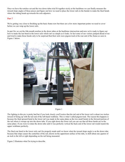
In part Six we cut the fish-mouth notches in the down tubes at the backbone intersection and now we're ready to figure out<br />
how to make the last bend in the lower rails which isn't as simple as it looks. In fact some of our visitors jumped ahead of me<br />
and tried to make those bends only to be surprised that their rails were pigeon-toed at the rear end of the frame as seen in<br />
Figure 1 below.<br />
Figure 1<br />
The lighting in this pic is pretty bad but if you look closely you'll notice that the tail end of the lower rail is about two inches<br />
inward of lining up with the tail end of the left-hand wishbone. This is what I called pigeon-toed. The reason this happens is<br />
because the final upward bend in the lower rail was made in the same plane as the two small bends in the forward portion of<br />
the rail where it sweeps up into the down tube. If you sight down the lower rail you can see that all three bends are in the<br />
same plane. If you were to rotate the down tube until it was perfectly vertical the back end of the lower rail would match the<br />
upper wishbone perfectly.<br />
The final rear bend in the lower rails can't be properly made until we know what the inward slope angle is on the down tube<br />
because that slope causes the centerline of the rail, drawn on the uppermost surface of the tube, to shift about one quarter of<br />
an inch to the left or right depending on the rail being measured.<br />
Figure 2 illustrates what I'm trying to describe.