Old School Chopper Frame Fabrication - Knucklebuster
Old School Chopper Frame Fabrication - Knucklebuster
Old School Chopper Frame Fabrication - Knucklebuster

You also want an ePaper? Increase the reach of your titles
YUMPU automatically turns print PDFs into web optimized ePapers that Google loves.
Regardless of the style or type of adjusters, plates or housings you finally decide to build it is imperative that they be installed<br />
in near perfect alignment with the motor, transmission and front wheel axle axis. You'll no doubt realize that I deliberately<br />
didn't say that they need to be installed in alignment with the frame itself because they don't, and in some cases shouldn't.<br />
It is almost impossible to build a 'perfectly' aligned frame with zero tolerances even if you're using a fairly accurate welding<br />
jig. Accumulated errors and welding distortion will inevitably creep in to the design. Consider yourself either very good or<br />
very lucky if your frame is within one-eighth of an inch square and plumb measured in every conceivable direction when its<br />
finally welded up prior to installation of the steering neck and axle plates which brings us to a problem of sequencing the<br />
fabrication.<br />
There are two schools of thought about necks and axle adjusters. One school holds that it's better to weld in the axle plates<br />
before you weld on the steering neck and the other holds that it's better to weld in the neck and fit the adjusters secondarily.<br />
I've done it both ways and haven't personally found one method superior to the other so I'll leave it up to you to decide which<br />
method produces better results on your own projects.<br />
For the purposes of this article we'll be installing the axle plates first.<br />
The axle plates, or adjuster boxes, if that's what you're building, have to be installed so that the rear axle holes or slots are<br />
situated in such a manner so that the axle itself, when it is 'adjusted' stays in the same plane and remains 'square' and 'plumb'<br />
with the front axle axis and the transmission output shaft sprocket.<br />
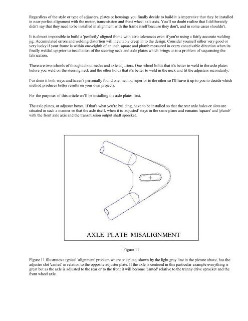
Figure 11<br />
Figure 11 illustrates a typical 'alignment' problem where one plate, shown by the light gray line in the picture above, has the<br />
adjuster slot 'canted' in relation to the opposite adjuster plate. If the axle is centered in this particular example everything is<br />
great but as the axle is adjusted to the rear or to the front it will become 'canted' relative to the tranny drive sprocket and the<br />
front wheel axle.