- Page 1 and 2:
Proceedings of the Second U.S. WATE
- Page 3 and 4:
Visualization of the Central Core o
- Page 5 and 6:
A Status Report on the Conceptual D
- Page 7 and 8:
SESSION 7 - CIVIL & INDUSTRIAL Chai
- Page 9 and 10:
Cutting Hard Rock With Abrasive-Ent
- Page 11 and 12:
frictional and piping component rel
- Page 13 and 14:
R = a1 ⋅ A1 A2 a2 I = 2H o Q o
- Page 15 and 16:
attenuation of the output. The tran
- Page 17 and 18:
Figure 1. Branch System Modulator F
- Page 19 and 20:
Figure 5. Modulation Response for B
- Page 21 and 22:
Figure 9. Modulation response for s
- Page 23 and 24:
can be used for any form of input.
- Page 25 and 26:
with a cylindrical shape to the jet
- Page 27 and 28:
m/s. The range of power found from
- Page 29 and 30:
Figure 3. Power vs nozzle diameter
- Page 31 and 32:
Figure 5. Frequency vs length of th
- Page 34 and 35:
NAME: Gerald Zink COMPANY: StoneAge
- Page 36 and 37:
modulatornozzle assembly. The ordin
- Page 38 and 39:
DISCUSSION OF FLUID MECHANICS The i
- Page 40 and 41:
This process serves to protect the
- Page 42 and 43:
For test purposes, these concrete b
- Page 44 and 45:
REFERENCES CITED 1. Barker, C. R.,
- Page 46 and 47:
FIGURE 4. INNER CORE OF PERCUSSIVE
- Page 48 and 49:
FIGURE 9. EXAMPLE OF HIGH-PRESSURE
- Page 50 and 51:
NAME: John E. Wolgamott COMPANY: St
- Page 52 and 53:
THE FOCUSED SHOCK TECHNlQUE FORPROD
- Page 54 and 55:
The reflected wave is thus also cyl
- Page 56 and 57:
neglected. The introduction of a co
- Page 58 and 59:
DISCUSSION NAME: George Savanick CO
- Page 60 and 61:
H’ mean shape factor Hj theoretic
- Page 62 and 63:
Required streamline curvature at th
- Page 64 and 65:
2 x 2 ≅ ( e − 2 p + w)/k2 (2-8)
- Page 66 and 67:
eliminating 2 n r 2 from equations
- Page 68 and 69:
approximation to the actual flow si
- Page 70 and 71:
skin friction coefficient but are c
- Page 72 and 73:
where: (H) = A1H 3 + A2H 2 + A3H +
- Page 74 and 75:
effect (< 0.5%) on coefficients of
- Page 76 and 77:
TABLE 5 Rei x 10 5 β 3 4 5 6 Po Po
- Page 78 and 79:
TABLE 6 D(mm) d o(mm) L t(mm) L f(m
- Page 80 and 81:
expanding rather than contracting a
- Page 82 and 83:
25. Weber, H.E., 1978, Boundary lay
- Page 84 and 85:
Figure 5. Wall velocity distributio
- Page 86 and 87:
Figure 9. Effect of nozzle design o
- Page 88 and 89:
Figure 12. CA+T Design Philosophy.
- Page 90 and 91:
Figure 16. Effect of inlet b 1 cond
- Page 92 and 93:
Figure 20. Relaminarization at nozz
- Page 94 and 95:
Figure 24. Pressure decay data. 88
- Page 96 and 97:
VISUALIZATION OF THE CENTRAL CORE O
- Page 98 and 99:
DISCUSSION Although employing the i
- Page 100 and 101:
5. Lambert, J. H., 1760, Photometri
- Page 102 and 103:
Figure 6. Spectral sensitivity curv
- Page 104 and 105:
NAME: W.C. Cooley COMPANY: Terraspa
- Page 106 and 107:
INTRODUCTION Pulsed liquid jets sho
- Page 108 and 109:
y=X ∨ P A dy = p p A p 2 (L c y=0
- Page 110 and 111:
Using equation (15), the value of X
- Page 112 and 113:
Thus about the first 10% of the dri
- Page 114 and 115:
Many design cases, including those
- Page 116 and 117:
surface spall occurred, resulting i
- Page 118 and 119:
Figure 3. Chamber pressure at pisto
- Page 120 and 121:
Figure 7. Effect of nozzle area rat
- Page 122 and 123:
Figure 11. Extrusion device schemat
- Page 124 and 125:
Figure 15. Typical chamber pressure
- Page 126 and 127:
DISCUSSION NAME: W. C. Cooley COMPA
- Page 128 and 129:
material which are, in turn, affect
- Page 130 and 131:
the water jet. This method was not
- Page 132 and 133:
where h is the depth of penetration
- Page 134 and 135:
obtained during this phase of the i
- Page 136 and 137:
observed that the smallest depth of
- Page 138 and 139:
Figure 2. Idealized Relationships b
- Page 140 and 141:
Figure 6. Penetration as a Function
- Page 142 and 143:
DEVELOPMENT OF VARIABLE DELIVERY TR
- Page 144 and 145:
THE STRUCTURE AND FUNCTION OF THE P
- Page 146 and 147:
The injection pressure can be contr
- Page 148 and 149:
ACKNOWLEDGEMENTS The authors gratef
- Page 150 and 151:
Figure 4. Theoretical required powe
- Page 152 and 153:
Figure 9. Variation of efficiency w
- Page 154 and 155:
THE "SKIPJACK" SEWER CLEANING NOZZL
- Page 156 and 157:
HYDRO-BLASTING SAFETY C.W. Adaway,
- Page 158 and 159:
Remember, your Hydro-Blasting work
- Page 160 and 161:
horizontal, sometimes vertical, and
- Page 162 and 163:
Figure 2. Safety Gear Figure 3. Tub
- Page 164 and 165:
DEVELOPMENTS IN CLEANING COKE OVEN
- Page 166 and 167:
causing chain breakages and the scr
- Page 168 and 169:
was encountered, then the rotation
- Page 170 and 171:
(C) Capital Expenditure: Material i
- Page 172 and 173:
Figure 9. Swivel coupling Figure 10
- Page 174 and 175:
OPTIMIZING JET CUTTING POWER FOR TU
- Page 176 and 177:
PRESSURE DROP (psi) ELEMENT Cv @10
- Page 178 and 179:
power output. Undersized nozzles re
- Page 180 and 181:
Subscripts n - Nozzle p - Pump t -
- Page 182 and 183:
Figure 1. Cutting effect as a funct
- Page 184 and 185:
CONSIDERATIONS IN THE COMPARISON OF
- Page 186 and 187:
pressure can be lowered to perhaps
- Page 188 and 189:
Figure 2: Fan jet issuing from a no
- Page 190 and 191:
DISCUSSION NAME: John Griffiths COM
- Page 192 and 193:
where Q = Flow rate - gpm D = Jet O
- Page 194 and 195:
Again, not limited to Newtonian flu
- Page 196 and 197:
REFERENCES 1. Brown, R.W. and Loper
- Page 198 and 199:
Table 2. Jet Cleaning Speeds and ot
- Page 200 and 201:
ANSWER: The utilization of the stat
- Page 202 and 203:
complexity and short component life
- Page 204 and 205:
Figure 4, for ap values ranging fro
- Page 206 and 207:
Decontamination Methods for rapidly
- Page 208 and 209:
a. “PULSER” b.”ORGAN-PIPE”
- Page 210 and 211:
Figure 5 - Removal rate for various
- Page 212 and 213:
DISCUSSION NAME: David A. Summers C
- Page 214 and 215:
DRILLING BORE HOLES IN COAL MINES U
- Page 216 and 217:
pile could not be judged as represe
- Page 218 and 219:
DISCUSSION NAME: David Summers COMP
- Page 220 and 221:
HYDRAULIC MINING EXPERIMENTS IN AN
- Page 222 and 223:
The monitor was fed pressurized wat
- Page 224 and 225:
The IH rig was considered to be sup
- Page 226 and 227:
REFERENCES 1. Okhrimenki, V. A., A.
- Page 228 and 229:
Figure 2. Jet cutting sandstone at
- Page 230 and 231:
Figure 5. Schematic plan view of In
- Page 232 and 233:
Figure 7. Suction Box. 226
- Page 234 and 235:
USE OF HIGH PRESSURE WATER JETS FOR
- Page 236 and 237:
flame torch to cut this block, redu
- Page 238 and 239:
the order of 360 rpm. Under these c
- Page 240 and 241:
Figure 3. Slot cut by jet at 11 o s
- Page 242 and 243:
JET-MINER SURFACE AND IN-SEAM TRIAL
- Page 244 and 245:
The hydraulic drive of the haulage
- Page 246 and 247:
The surface trials had have the obj
- Page 248 and 249:
Figure 2. Experimental version. Fig
- Page 250 and 251:
Figure. 7 Jet-Miner prototype Figur
- Page 252 and 253:
SOME PATTERNS OF TECHNOLOGY TRANSFE
- Page 254 and 255:
Development of High Pressure_Techno
- Page 256 and 257:
configurations, the design of an op
- Page 258 and 259:
and public sectors. After a haitus
- Page 260 and 261:
Souder, W.E. and Evans, R.J., "The
- Page 262 and 263:
Figure 5. Technological achievement
- Page 264 and 265:
Table 3. Perceived disadvantages of
- Page 266 and 267:
already been, or is being applied w
- Page 268 and 269:
Using the requirements profile and
- Page 270 and 271:
ant hose combination, a guiding sys
- Page 272 and 273:
HYDRAULIC MINING TESTS Site selecti
- Page 274 and 275:
SAFETY All operations were carried
- Page 276 and 277:
TABLE V. Categories of Jet Mining D
- Page 278 and 279:
Figure 2. Generalized geologic prof
- Page 280 and 281:
SECONDARY FRAGMENTATION WITH WATER
- Page 282 and 283:
do possess a maximum point (Fig. 8)
- Page 284 and 285:
Figure 4. Rossin-Rammler plot. Figu
- Page 286 and 287:
Figure 8. Non-dimensional plot for
- Page 288 and 289:
HYDRAULIC COAL MINING SYSTEM Typica
- Page 290 and 291:
Figure 4. (From ref. 1) DISCUSSION
- Page 292 and 293:
INTRODUCTION Developing an unique t
- Page 294 and 295:
The coefficients "b " in Eq. (1) ca
- Page 296 and 297:
By the end of 1982, a total of more
- Page 298 and 299:
Figure 4. Cutting ability of swing-
- Page 300 and 301:
Figure 10. An operating performance
- Page 302 and 303:
for an abrasive, the abrasive parti
- Page 304 and 305:
the particles, while at slower spee
- Page 306 and 307:
to break away the remaining segment
- Page 308 and 309:
Table 1. Concrete saw technology. T
- Page 310 and 311:
NAME: Tom Brunsing COMPANY: Foster-
- Page 312 and 313:
FEASIBILITY STUDY OF CUTTING SOME M
- Page 314 and 315:
hydraulic power required to cut thr
- Page 316 and 317:
pressure was varied from 103 to 310
- Page 318 and 319:
2.1 Heading and gutting fresh cod f
- Page 320 and 321:
Figure 5. The cuts surface of a blo
- Page 322 and 323:
Figure 17. Cuts made across the cla
- Page 324 and 325:
JET NOTCHING USED IN THE CONSTRUCTI
- Page 326 and 327:
Bottom notch diameter was determine
- Page 328 and 329:
σ H = in-situ stress in the horizo
- Page 330 and 331:
Figure 3. Final block displacement.
- Page 332 and 333:
Figure 8. Comparison of Slurry Pump
- Page 334 and 335:
THE FURTHER DEVELOPMENT OF AN UNDER
- Page 336 and 337:
use taps or hydrants. To achieve th
- Page 338 and 339:
supply line. It was determined that
- Page 340 and 341:
The rotating head requires major mo
- Page 342 and 343:
Figure 4. System field test set-up
- Page 344 and 345:
Figure 10. Bentonite drilled clay s
- Page 346 and 347:
MECHANICAL TOOLS Cutting Tool Energ
- Page 348 and 349:
Ψ = cos −1 ⎧ ⎪ ⎪ ⎨ ⎪
- Page 350 and 351:
mode also contributes to chip flush
- Page 352 and 353:
NAME: Simon Johnson COMPANY: Newcas
- Page 354 and 355:
ROLLER TOOLS COMBINED WITH HIGH-PRE
- Page 356 and 357:
Various designs and applications ar
- Page 358 and 359:
Figure 1. Full-face tunneling machi
- Page 360 and 361:
Figure 11. roadway profile cutting
- Page 362 and 363:
Figure 19. High-pressure water jet
- Page 364 and 365: DESIGN AND OPERATION OF TWO LARGE-S
- Page 366 and 367: The hydraulic system for the thrust
- Page 368 and 369: Results of Trial Tests As part of m
- Page 370 and 371: cutting rates, degree of bit wear,
- Page 372 and 373: Overall approximate Weight: Basic M
- Page 374 and 375: Figure 5. 3 ft. diameter laboratory
- Page 376 and 377: nozzle diameter and cutting speed w
- Page 378 and 379: 2. Cutting Speed The influence of c
- Page 380 and 381: energy it effects an increase in me
- Page 382 and 383: Tip angle (degrees) 87 Off-set angl
- Page 384 and 385: Figure 5. Figure 6. Figure 7 Figure
- Page 386 and 387: Figure 17. Figure 18. Figure 19. Fi
- Page 388 and 389: SCHEMES OF COAL MASSIF BREAKAGE BY
- Page 390 and 391: out thoroughly an efficient scheme
- Page 392 and 393: Research analysis has proved that t
- Page 394 and 395: DEPENDENCE OF POWER INDICES OF COMB
- Page 396 and 397: The experiments have shown how the
- Page 398 and 399: K Ay = coefficient correcting for f
- Page 400 and 401: Figure 1. Schemes of combined break
- Page 402 and 403: Figure 5. Dependence of specific en
- Page 404 and 405: Figure 12. Percentage of grade R -6
- Page 406 and 407: Figure 1. Particle size analysis. T
- Page 408 and 409: NAME: Dr. Henkel COMPANY: Bergbau-F
- Page 410 and 411: presented. This study, of course, i
- Page 412 and 413: identifying a general trend for the
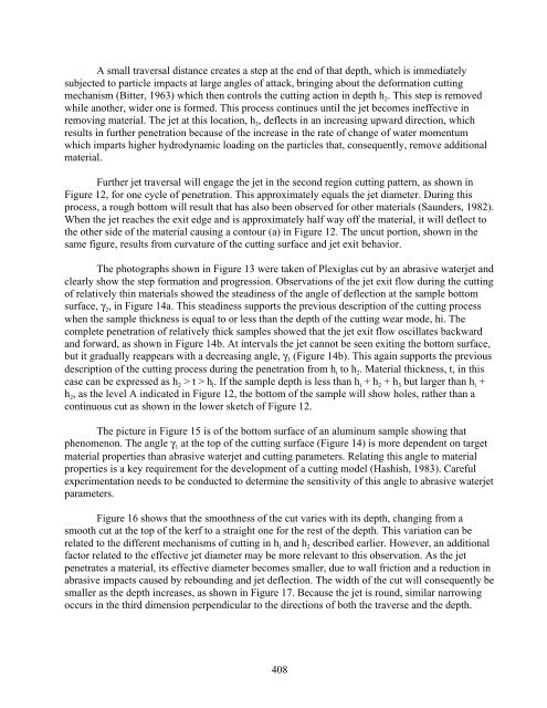
- Page 416 and 417: In some situations, especially in c
- Page 418 and 419: Figure 1. Abrasive waterjet nozzles
- Page 420 and 421: Figure 8. Effect of standoff distan
- Page 422 and 423: Figure 13. Abrasive waterjet cuts i
- Page 424 and 425: CUTTING WITH ABRASIVE WATERJETS M.
- Page 426 and 427: 3.3 Abrasive Feed Systems For abras
- Page 428 and 429: Because of the large number of infl
- Page 430 and 431: due to wear. Although actual operat
- Page 432 and 433: from this new technology. Table 2 l
- Page 434 and 435: Table 1. materials cut by abrasive
- Page 436 and 437: Figure 1. Abrasive waterjet nozzles
- Page 438 and 439: a) kerfs in mild steel b) S.S. 15.5
- Page 440 and 441: a) circle cutting in glass b) lamin
- Page 442 and 443: DISCUSSION NAME: Andrew F. Conn COM
- Page 444 and 445: CUTTING HARD ROCK WITH ABRASIVE-ENT
- Page 446 and 447: slurry nozzle. Testing at water pre
- Page 448 and 449: DISCUSSION OF TEST RESULTS Jet Conf
- Page 450 and 451: materials. The flexibility in nozzl
- Page 452 and 453: pressure can be wiped out if diffic
- Page 454 and 455: 9. Maurer, W.C., and Heilheckler, J
- Page 456 and 457: Figure 5. Effect of abrasive feed r
- Page 458 and 459: Figure 9. Accumulated depth of mult
- Page 460 and 461: Figure 13. Close-up view of quartzi
- Page 462 and 463: ABRASIVE INJECTION USAGE IN THE UNI
- Page 464 and 465:
sudden changes in the feed rate eff
- Page 466 and 467:
or the abrasive must be manually to
- Page 468 and 469:
clog; there not being sufficient ar
- Page 470 and 471:
CODE OF PRACTICE FOR THE USE OF ABR
- Page 472 and 473:
Figure 5. Water abrasive cleaning h
- Page 474 and 475:
Figure 15. 360 0 abrasive pipe clea
- Page 476 and 477:
ECONOMIC CONSIDERATIONS IN WATER JE
- Page 478 and 479:
Other criteria to be considered in
- Page 480 and 481:
3 MANUAL METHODS OF JET CLEANING &
- Page 482 and 483:
contractor with old, unsafe, equipm
- Page 484 and 485:
Figure 1. Showing the increased cos
- Page 486 and 487:
Figure 8. Automatic tube bundle cle
- Page 488 and 489:
ackground to the subsequent coopera
- Page 490 and 491:
The molecules of SUPER-WATER posses
- Page 492 and 493:
shaken just before use. SUPERWATER
- Page 494:
26. Bednarz, L.P., "Effects of Poly


