Influence of the natural aluminium oxide layer on ... - ALU-WEB.DE
Influence of the natural aluminium oxide layer on ... - ALU-WEB.DE
Influence of the natural aluminium oxide layer on ... - ALU-WEB.DE

Create successful ePaper yourself
Turn your PDF publications into a flip-book with our unique Google optimized e-Paper software.
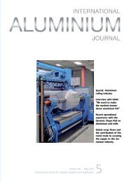
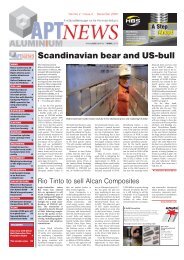
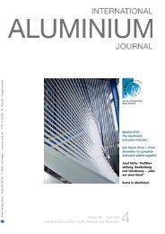
Fig. 3: Experimental setup for extrusi<strong>on</strong> with subsequent electromagnetic compressi<strong>on</strong><br />
tween <str<strong>on</strong>g>the</str<strong>on</strong>g> workpiece and <str<strong>on</strong>g>the</str<strong>on</strong>g> tool coil during<br />
<str<strong>on</strong>g>the</str<strong>on</strong>g> compressi<strong>on</strong> process can be neglected. For<br />
example, with an exiting speed <str<strong>on</strong>g>of</str<strong>on</strong>g> 50 m/min,<br />
and 100 μs for <str<strong>on</strong>g>the</str<strong>on</strong>g> electromagnetic forming<br />
process, a relative movement between <str<strong>on</strong>g>the</str<strong>on</strong>g><br />
extrudate pr<str<strong>on</strong>g>of</str<strong>on</strong>g>ile and <str<strong>on</strong>g>the</str<strong>on</strong>g> tool coil <str<strong>on</strong>g>of</str<strong>on</strong>g> about<br />
160 μm results, which meets <str<strong>on</strong>g>the</str<strong>on</strong>g> geometrical<br />
tolerance field <str<strong>on</strong>g>of</str<strong>on</strong>g> macroscopic forming processes.<br />
Therefore, <str<strong>on</strong>g>the</str<strong>on</strong>g> applicati<strong>on</strong> <str<strong>on</strong>g>of</str<strong>on</strong>g> electromagnetic<br />
compressi<strong>on</strong> subsequent to extrusi<strong>on</strong><br />
is possible without a compensati<strong>on</strong> <str<strong>on</strong>g>of</str<strong>on</strong>g> <str<strong>on</strong>g>the</str<strong>on</strong>g><br />
relative speed between <str<strong>on</strong>g>the</str<strong>on</strong>g> workpiece and <str<strong>on</strong>g>the</str<strong>on</strong>g><br />
tooling.<br />
To integrate both processes, a tool coil for<br />
compressi<strong>on</strong> was positi<strong>on</strong>ed behind <str<strong>on</strong>g>the</str<strong>on</strong>g> die<br />
exit and coaxial to <str<strong>on</strong>g>the</str<strong>on</strong>g> extrudate in order to<br />
reduce <str<strong>on</strong>g>the</str<strong>on</strong>g> workpiece cross secti<strong>on</strong> locally<br />
(Fig. 1). Additi<strong>on</strong>ally, a counter die in <str<strong>on</strong>g>the</str<strong>on</strong>g> shape<br />
<str<strong>on</strong>g>of</str<strong>on</strong>g> a mandrel can be mounted to <str<strong>on</strong>g>the</str<strong>on</strong>g> mandrel<br />
<str<strong>on</strong>g>of</str<strong>on</strong>g> a porthole extrusi<strong>on</strong> die, which extended<br />
into <str<strong>on</strong>g>the</str<strong>on</strong>g> tool coil (Jäger et al., 2009). By this,<br />
besides achieving a more defined geometry in<br />
comparis<strong>on</strong> to a free forming operati<strong>on</strong>, an<br />
increase <str<strong>on</strong>g>of</str<strong>on</strong>g> <str<strong>on</strong>g>the</str<strong>on</strong>g> geometrical complexity <str<strong>on</strong>g>of</str<strong>on</strong>g> locally<br />
compressed areas can be achieved.<br />
For processing open secti<strong>on</strong>s, like L-, T<br />
and double-T-shaped pr<str<strong>on</strong>g>of</str<strong>on</strong>g>iles, a rolling pro-<br />
cess was developed. By executing <str<strong>on</strong>g>the</str<strong>on</strong>g> subsequent<br />
forming operati<strong>on</strong> as a rolling process,<br />
<str<strong>on</strong>g>the</str<strong>on</strong>g> c<strong>on</strong>tinuous run out <str<strong>on</strong>g>of</str<strong>on</strong>g> <str<strong>on</strong>g>the</str<strong>on</strong>g> pr<str<strong>on</strong>g>of</str<strong>on</strong>g>ile can be<br />
taken into account.<br />
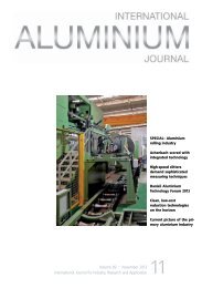
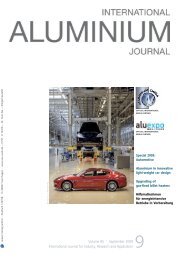
Fig. 4: Dimensi<strong>on</strong>s <str<strong>on</strong>g>of</str<strong>on</strong>g> <str<strong>on</strong>g>the</str<strong>on</strong>g> mandrel for electromagnetic forming<br />
A special rolling stand was developed and<br />
mounted behind <str<strong>on</strong>g>the</str<strong>on</strong>g> extrusi<strong>on</strong> platen <str<strong>on</strong>g>of</str<strong>on</strong>g> an<br />
extrusi<strong>on</strong> press, allowing <str<strong>on</strong>g>the</str<strong>on</strong>g> c<strong>on</strong>tinuous forming<br />
<str<strong>on</strong>g>of</str<strong>on</strong>g> <str<strong>on</strong>g>the</str<strong>on</strong>g> outgoing extrusi<strong>on</strong> pr<str<strong>on</strong>g>of</str<strong>on</strong>g>iles. The<br />
rollers mesh toge<str<strong>on</strong>g>the</str<strong>on</strong>g>r with sinusoidal teeth,<br />
creating a corrugated c<strong>on</strong>tour <strong>on</strong> <str<strong>on</strong>g>the</str<strong>on</strong>g> web <str<strong>on</strong>g>of</str<strong>on</strong>g><br />
a c<strong>on</strong>tinuously fed I-beam-shaped pr<str<strong>on</strong>g>of</str<strong>on</strong>g>ile. The<br />
c<strong>on</strong>tour <str<strong>on</strong>g>of</str<strong>on</strong>g> <str<strong>on</strong>g>the</str<strong>on</strong>g> forming dies stores <str<strong>on</strong>g>the</str<strong>on</strong>g> desired<br />
geometry <str<strong>on</strong>g>of</str<strong>on</strong>g> <str<strong>on</strong>g>the</str<strong>on</strong>g> workpiece. As <str<strong>on</strong>g>the</str<strong>on</strong>g> exit speed <str<strong>on</strong>g>of</str<strong>on</strong>g><br />
<str<strong>on</strong>g>the</str<strong>on</strong>g> extrudate varies, compensati<strong>on</strong> strategies<br />
have to be provided. For this, <str<strong>on</strong>g>the</str<strong>on</strong>g> rolling stand<br />
was swivel-mounted and <str<strong>on</strong>g>the</str<strong>on</strong>g> rotati<strong>on</strong>al speed<br />
<str<strong>on</strong>g>of</str<strong>on</strong>g> <str<strong>on</strong>g>the</str<strong>on</strong>g> rollers was adapted permanently (Fig. 2).<br />
Extrusi<strong>on</strong> and electromagnetic forming<br />
A test rig for evaluating <str<strong>on</strong>g>the</str<strong>on</strong>g> c<strong>on</strong>cept <str<strong>on</strong>g>of</str<strong>on</strong>g> <str<strong>on</strong>g>the</str<strong>on</strong>g><br />
integrati<strong>on</strong> <str<strong>on</strong>g>of</str<strong>on</strong>g> an electromagnetic compressi<strong>on</strong><br />
step subsequent to extrusi<strong>on</strong> was built (Fig. 3).<br />
A tool coil was positi<strong>on</strong>ed behind <str<strong>on</strong>g>the</str<strong>on</strong>g> die exit<br />
in order to reduce <str<strong>on</strong>g>the</str<strong>on</strong>g> workpiece cross secti<strong>on</strong><br />
locally. To adapt <str<strong>on</strong>g>the</str<strong>on</strong>g> tool coil and <str<strong>on</strong>g>the</str<strong>on</strong>g> extrudate<br />
geometry, a field shaper made out <str<strong>on</strong>g>of</str<strong>on</strong>g> a<br />
CuCrZr-alloy, electrically insulated with a<br />
polyimide foil, is used. Bey<strong>on</strong>d shaping and<br />
c<strong>on</strong>centrating <str<strong>on</strong>g>of</str<strong>on</strong>g> <str<strong>on</strong>g>the</str<strong>on</strong>g> electromagnetic field, <str<strong>on</strong>g>the</str<strong>on</strong>g><br />
field shaper also prevents an overheating <str<strong>on</strong>g>of</str<strong>on</strong>g><br />
<str<strong>on</strong>g>the</str<strong>on</strong>g> tool coil by <str<strong>on</strong>g>the</str<strong>on</strong>g>rmal radiati<strong>on</strong> <str<strong>on</strong>g>of</str<strong>on</strong>g> <str<strong>on</strong>g>the</str<strong>on</strong>g> processed<br />
hot extrudate. To assure a uniform air<br />
gap between <str<strong>on</strong>g>the</str<strong>on</strong>g> field shaper and <str<strong>on</strong>g>the</str<strong>on</strong>g> workpiece<br />
guiding rollers made out <str<strong>on</strong>g>of</str<strong>on</strong>g> brass are ar-<br />
EXTRUSION<br />
ranged pairwise at <str<strong>on</strong>g>the</str<strong>on</strong>g> inlet and run-out side<br />
<str<strong>on</strong>g>of</str<strong>on</strong>g> <str<strong>on</strong>g>the</str<strong>on</strong>g> tool coil. For heat treating <str<strong>on</strong>g>of</str<strong>on</strong>g> <str<strong>on</strong>g>the</str<strong>on</strong>g> extruded<br />
and subsequently hot deformed workpieces<br />
made <str<strong>on</strong>g>of</str<strong>on</strong>g> heat treatable alloys, an additi<strong>on</strong>al<br />
quenching setup was positi<strong>on</strong>ed behind<br />
<str<strong>on</strong>g>the</str<strong>on</strong>g> tool coil. Atomizing nozzles are located<br />
around <str<strong>on</strong>g>the</str<strong>on</strong>g> press axis providing air atomized<br />
water mist streams. To use <str<strong>on</strong>g>the</str<strong>on</strong>g> press heat <str<strong>on</strong>g>of</str<strong>on</strong>g><br />
extrusi<strong>on</strong> for <str<strong>on</strong>g>the</str<strong>on</strong>g> subsequent <str<strong>on</strong>g>the</str<strong>on</strong>g>rmo-mechanical<br />
processing steps efficiently, <str<strong>on</strong>g>the</str<strong>on</strong>g> whole<br />
setup is designed compactly. From <str<strong>on</strong>g>the</str<strong>on</strong>g> die exit<br />
to <str<strong>on</strong>g>the</str<strong>on</strong>g> quenching, <str<strong>on</strong>g>the</str<strong>on</strong>g> whole setup has a length<br />
<str<strong>on</strong>g>of</str<strong>on</strong>g> less than <strong>on</strong>e meter.<br />
Experimental trials were performed using<br />
a 250-t<strong>on</strong> direct extrusi<strong>on</strong> press (Collin<br />
PLA250t) and a pulse power generator (Maxwell-Magneform<br />
series 7000). Solenoid coils<br />
fabricated from copper and embedded in a<br />
fibre-reinforced resin were used as tool coils<br />
(Poynting GmbH). Using an EN AW-6082 <str<strong>on</strong>g>aluminium</str<strong>on</strong>g><br />
alloy, a porthole extrusi<strong>on</strong> die and a<br />
squared field shaper, a squared hollow pr<str<strong>on</strong>g>of</str<strong>on</strong>g>ile<br />
(30 x 30 x 1.8 mm) was extruded with an exiting<br />
speed <str<strong>on</strong>g>of</str<strong>on</strong>g> about 16 mm/s while compressi<strong>on</strong><br />
by electromagnetic forming was applied<br />
periodically in intervals <str<strong>on</strong>g>of</str<strong>on</strong>g> approximately<br />
10s. Semi-finished products with local bulges<br />
arranged around <str<strong>on</strong>g>the</str<strong>on</strong>g> circumference <str<strong>on</strong>g>of</str<strong>on</strong>g> <str<strong>on</strong>g>the</str<strong>on</strong>g><br />
squared tube can be produced.<br />
In order to expand <str<strong>on</strong>g>the</str<strong>on</strong>g> range <str<strong>on</strong>g>of</str<strong>on</strong>g> geometrical<br />
shapes with cross-secti<strong>on</strong>s o<str<strong>on</strong>g>the</str<strong>on</strong>g>r than that<br />
<str<strong>on</strong>g>of</str<strong>on</strong>g> <str<strong>on</strong>g>the</str<strong>on</strong>g> extruded <str<strong>on</strong>g>aluminium</str<strong>on</strong>g>, a mandrel can be<br />
used to define <str<strong>on</strong>g>the</str<strong>on</strong>g> cross secti<strong>on</strong> geometry. A<br />
squared mandrel for <str<strong>on</strong>g>the</str<strong>on</strong>g> processing <str<strong>on</strong>g>of</str<strong>on</strong>g> a round<br />
tube was chosen and specially designed to prevent<br />
force fit between <str<strong>on</strong>g>the</str<strong>on</strong>g> workpiece and <str<strong>on</strong>g>the</str<strong>on</strong>g><br />
die (Fig. 4). By using a squared field shaper,<br />
with an aperture <str<strong>on</strong>g>of</str<strong>on</strong>g> 43.4 x 43.4 mm and a<br />
length <str<strong>on</strong>g>of</str<strong>on</strong>g> 27 mm <str<strong>on</strong>g>of</str<strong>on</strong>g> <str<strong>on</strong>g>the</str<strong>on</strong>g> c<strong>on</strong>centrator, in combinati<strong>on</strong><br />
with <str<strong>on</strong>g>the</str<strong>on</strong>g> extrusi<strong>on</strong> <str<strong>on</strong>g>of</str<strong>on</strong>g> a round tube<br />
(Ø 40 x 2 mm) fur<str<strong>on</strong>g>the</str<strong>on</strong>g>r trials were performed.<br />
In this combinati<strong>on</strong> <str<strong>on</strong>g>of</str<strong>on</strong>g> field shaper, workpiece<br />
and mandrel an adapted air gap and<br />
pressure distributi<strong>on</strong> al<strong>on</strong>g <str<strong>on</strong>g>the</str<strong>on</strong>g> workpiece<br />
circumference can be achieved which helps<br />
to prevent a force fit between <str<strong>on</strong>g>the</str<strong>on</strong>g> extrudate<br />
and <str<strong>on</strong>g>the</str<strong>on</strong>g> mandrel. In order to character-<br />
ize <str<strong>on</strong>g>the</str<strong>on</strong>g> forming results when a mandrel was<br />
used as a form defining tool, an experimental<br />
study was performed at charging energies<br />
<str<strong>on</strong>g>of</str<strong>on</strong>g> 6.4 kJ, 8 kJ and 8.8 kJ. To measure <str<strong>on</strong>g>the</str<strong>on</strong>g><br />
high speed current pulse in <str<strong>on</strong>g>the</str<strong>on</strong>g> tool coil a<br />
Rogowski coil was used. The best forming result/geometrical<br />
accuracy could be achieved at<br />
a charging energy <str<strong>on</strong>g>of</str<strong>on</strong>g> 8 kJ. For this a maximum<br />
coil current amplitude <str<strong>on</strong>g>of</str<strong>on</strong>g> 62 kA and frequency<br />
<str<strong>on</strong>g>of</str<strong>on</strong>g> <str<strong>on</strong>g>the</str<strong>on</strong>g> discharging current <str<strong>on</strong>g>of</str<strong>on</strong>g> 4.5 kHz were detected.<br />
To prevent damage by overheating <str<strong>on</strong>g>of</str<strong>on</strong>g><br />
<str<strong>on</strong>g>the</str<strong>on</strong>g> tool coil and <str<strong>on</strong>g>the</str<strong>on</strong>g> electrical isolati<strong>on</strong>, <str<strong>on</strong>g>the</str<strong>on</strong>g><br />
field shaper was cooled by compressed air<br />
<strong>ALU</strong>MINIUM · EAC CONGRESS 2011 41