Advanced Building Simulation
Advanced Building Simulation
Advanced Building Simulation
Create successful ePaper yourself
Turn your PDF publications into a flip-book with our unique Google optimized e-Paper software.
96 Hensen<br />
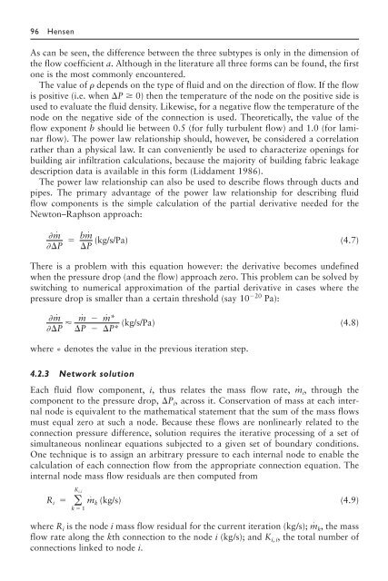
As can be seen, the difference between the three subtypes is only in the dimension of<br />
the flow coefficient a. Although in the literature all three forms can be found, the first<br />
one is the most commonly encountered.<br />
The value of � depends on the type of fluid and on the direction of flow. If the flow<br />
is positive (i.e. when �P � 0) then the temperature of the node on the positive side is<br />
used to evaluate the fluid density. Likewise, for a negative flow the temperature of the<br />
node on the negative side of the connection is used. Theoretically, the value of the<br />
flow exponent b should lie between 0.5 (for fully turbulent flow) and 1.0 (for laminar<br />
flow). The power law relationship should, however, be considered a correlation<br />
rather than a physical law. It can conveniently be used to characterize openings for<br />
building air infiltration calculations, because the majority of building fabric leakage<br />
description data is available in this form (Liddament 1986).<br />
The power law relationship can also be used to describe flows through ducts and<br />
pipes. The primary advantage of the power law relationship for describing fluid<br />
flow components is the simple calculation of the partial derivative needed for the<br />
Newton–Raphson approach:<br />
�m˙<br />
��P<br />
(4.7)<br />
There is a problem with this equation however: the derivative becomes undefined<br />
when the pressure drop (and the flow) approach zero. This problem can be solved by<br />
switching to numerical approximation of the partial derivative in cases where the<br />
pressure drop is smaller than a certain threshold (say 10 �20 Pa):<br />
�m˙<br />
��P<br />
�<br />
m˙ � m˙ *<br />
�<br />
(kg/s/Pa)<br />
�P � �P*<br />
where * denotes the value in the previous iteration step.<br />
(4.8)<br />
4.2.3 Network solution<br />
Each fluid flow component, i, thus relates the mass flow rate, m˙ i,<br />
through the<br />
component to the pressure drop, �Pi, across it. Conservation of mass at each internal<br />
node is equivalent to the mathematical statement that the sum of the mass flows<br />
must equal zero at such a node. Because these flows are nonlinearly related to the<br />
connection pressure difference, solution requires the iterative processing of a set of<br />
simultaneous nonlinear equations subjected to a given set of boundary conditions.<br />
One technique is to assign an arbitrary pressure to each internal node to enable the<br />
calculation of each connection flow from the appropriate connection equation. The<br />
internal node mass flow residuals are then computed from<br />
R i � � K i,i<br />
k � 1<br />
bm˙<br />
(kg/s/Pa)<br />
�P<br />
m˙ k (kg/s)<br />
(4.9)<br />
where Ri is the node i mass flow residual for the current iteration (kg/s); m˙ k,<br />
the mass<br />
flow rate along the kth connection to the node i (kg/s); and Ki, i, the total number of<br />
connections linked to node i.


