Advanced Building Simulation
Advanced Building Simulation
Advanced Building Simulation

Create successful ePaper yourself
Turn your PDF publications into a flip-book with our unique Google optimized e-Paper software.
168 Mahdavi<br />
Exterior light redirection louvers<br />
EL1<br />
E E1 1<br />
•<br />
t t1 1<br />
Local hot<br />
water valve<br />
Electric EL3<br />
light<br />
EL5<br />
EL2<br />
Space 1<br />
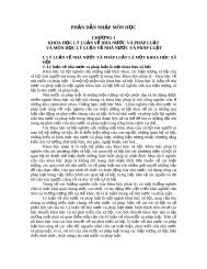
Figure 7.6 Schematic floor plan of the test spaces.<br />
DC<br />
EL1<br />
DC<br />
EL2<br />
DC<br />
EL3<br />
E 1<br />
DC<br />
EL4<br />
DC<br />
Va1<br />
EL4 EL6<br />
DC<br />
Lo1<br />
Workstation<br />
surface<br />
Space 2<br />
controlled by a DC-EL. Similarly, both the local valve state and the louver state<br />
influence the temperature in Space-1 (t 1). Analogous assumptions apply to Space-2.<br />
Once the control zones (controlled entities) have been defined, the generation rules<br />
can be applied to the control problem as illustrated in Figure 7.7, resulting in the representation<br />
of Figure 7.8. A summary of the application of rules 1, 2, and 3 in this case<br />
is shown in Table 7.2. As to the application of rule 1, four nodes, namely DC-EL1,<br />
EL2, EL3, and EL4 are of the same device type and all impact sensor E 1. Thus, an<br />
MC is needed to coordinate their action: MC-EL_1. Similarly, regarding the application<br />
of rule 2, both DC-Lo1 and DC-Va1 impact the temperature of Space-1. Thus,<br />
MC-Lo_Va_1 is needed to coordinate their action. As to rule 3, four MC nodes control<br />
the DC-Lo1 node. Thus, their actions must be coordinated by an MC of second<br />
order, namely MC-II EL_Lo_Va_1.<br />
In the above example, rules 1, 2, and 3 were applied to the control problem to construct<br />
the representation. Using this methodology, a scheme of distributed, hierarchical<br />
control nodes can be constructed. In certain cases, however, the control problem<br />
contains characteristics that cause the model not to converge toward a single top-level<br />
controller. In these cases, rules 4 and 5 can be applied to ensure convergence. Rule 4<br />
is used to ensure that model functionality is not duplicated. Thereby, the means of<br />
detecting a duplicated node lies in the node name. Since the application of rule 4 may<br />
DC<br />
Va2<br />
DC<br />
EL5<br />
DC<br />
EL6<br />
E E2 2<br />
•<br />
t t2 2<br />
DC<br />
EL7<br />
Figure 7.7 Association between sensors and devices (cp. text and Figure 7.6).<br />
t 1<br />
t 2<br />
E 2<br />
DC<br />
EL8<br />
EL7<br />
EL8