Advanced Building Simulation
Advanced Building Simulation
Advanced Building Simulation

You also want an ePaper? Increase the reach of your titles
YUMPU automatically turns print PDFs into web optimized ePapers that Google loves.
124 Chen and Zhai<br />
and � k�1.0, � ��1.3, C �1�1.44, and C �2�1.92 are empirical constants. The<br />
two-equation k–� model is most popular but not the simplest one. The simplest ones<br />
are zero-equation turbulence models, such as the constant viscosity model and the one<br />
proposed by Chen and Xu (1998). The constant viscosity model and zero-equation<br />
models do not solve turbulence quantities by transport equations.<br />
Be it LES or RANS modeling, the abovementioned equations cannot be solved analytically<br />
because they are highly nonlinear and interrelated. However, they can be<br />
solved numerically on a computer by discretizing them properly with an appropriate<br />
algorithm. Many textbooks have been devoted to this topic. Due to limited space<br />
available, this chapter does not discuss this issue here. Finally, boundary conditions<br />
must be specified in order to make the equations solvable for a specific problem of<br />
indoor environment.<br />
If one has used a CFD program with the abovementioned equations and specified<br />
boundary conditions for a flow problem, can one trust the results obtained? The<br />
following section will use an example to illustrate how one could obtain CFD results<br />
for an indoor environment problem and how one could evaluate the correctness of<br />
the results.<br />
5.3 <strong>Simulation</strong> and analysis<br />
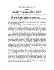
The following example is a study of indoor air and contaminant distribution in a room<br />
with displacement ventilation, as shown in Figure 5.1. The room was 5.16m long,<br />
3.65m wide, and 2.43m high. Cold air was supplied through a diffuser in the lower<br />
part of a room, and warm air was exhausted at the ceiling level. The two-person office<br />
contained many heated and unheated objects, such as occupants, lighting, computers,<br />
and furniture. For this case, Yuan et al. (1999) measured the air temperature, air<br />
velocity, and contaminant concentration by using SF 6 as a tracer-gas. The tracer-gas<br />
was used to simulate contaminant emissions from the two occupants, such as CO 2.<br />
The temperature of the inlet airflow from the diffuser was 17.0�C and the ventilation<br />
rate was 183m 3 /h. The total heat sources in the room were 636W.<br />
Y<br />
Z<br />
X<br />
Table<br />
External window<br />
Computer<br />
Furniture<br />
Lights<br />
Exhaust<br />
Occupant<br />
Occupant<br />
Figure 5.1 The schematic of a room with mixed convection flow.<br />
Diffuser<br />
Computer<br />
Furniture<br />
Table