- Page 2:
Advanced Building Simulation
- Page 5 and 6:
First published 2003 by Spon Press
- Page 7 and 8:
vi Contents 8 Developments in inter
- Page 9 and 10:
viii Figures 3.12 Relation between
- Page 11 and 12:
x Figures 8.14 Workflow Modeling Wi
- Page 13 and 14:
Contributors D. Michelle Addington,
- Page 16 and 17:
Prologue Introduction and overview
- Page 18 and 19:
Prologue 3 two topics that represen
- Page 20 and 21:
Trends in building simulation 5 com
- Page 22 and 23:
Reality Space averaged treatment of
- Page 24 and 25:
Pervasive/invisible Web-enabled Des
- Page 26 and 27:
Trends in building simulation 11 in
- Page 28 and 29:
Trends in building simulation 13 ea
- Page 30 and 31:
Trends in building simulation 15 ba
- Page 32 and 33:
Trends in building simulation 17 1.
- Page 34 and 35:
Trends in building simulation 19 th
- Page 36 and 37:
and predictive simulation-based con
- Page 38 and 39:
Trends in building simulation 23 Fu
- Page 40 and 41:
Chapter 2 Uncertainty in building s
- Page 42 and 43:
Uncertainty in building simulation
- Page 44 and 45:
This completes the outline of the c
- Page 46 and 47:
and inputs may be a formidable task
- Page 48 and 49:
Kleijnen (1997), Reedijk (2000), an
- Page 50 and 51:
Table 2.1 Categories of uncertain m
- Page 52 and 53:
∆C p (-) 1.6 1.2 0.8 0.4 0.0 -0.4
- Page 54 and 55:
Uncertainty in building simulation
- Page 56 and 57:
S d (h) 80 60 40 20 0 -80 2 Uncerta
- Page 58 and 59:
2.4.2 Uncertainty in wind pressure
- Page 60 and 61:
an experiment involving structured
- Page 62 and 63:
Uncertainty in building simulation
- Page 64 and 65:
Uncertainty in building simulation
- Page 66 and 67:
with their uncertainties, in terms
- Page 68 and 69:
Table 2.5 Expected utilities for de
- Page 70 and 71:
y a performance gain on another asp
- Page 72 and 73:
Uncertainty in building simulation
- Page 74 and 75:
Uncertainty in building simulation
- Page 76 and 77:
Simulation and uncertainty: weather
- Page 78 and 79:
Simulation and uncertainty: weather
- Page 80 and 81:
Simulation and uncertainty: weather
- Page 82 and 83:
makes every month normalized to a z
- Page 84 and 85:
Dry-bulb temperature (°F) 60 50 40
- Page 86 and 87:
(b) Compute today’s average tempe
- Page 88 and 89:
Simulation and uncertainty: weather
- Page 90 and 91:
ackward. First, the average daily h
- Page 92 and 93:
a��sin(�)* ln[I SC * � D] (
- Page 94 and 95:
H = Total daily horizontal insolati
- Page 96 and 97:
Temperature (°C) or wind speed (m/
- Page 98 and 99:
Horizontal insolation (MJ/m 2 /day)
- Page 100 and 101:
References Simulation and uncertain
- Page 102 and 103:
Chapter 4 Integrated building airfl
- Page 104 and 105:
(a) (b) zone 6 5 4 3 2 1 3 1 Pre-he
- Page 106 and 107:
a different physical state variable
- Page 108 and 109:
West Zone n Zone m Figure 4.5 Examp
- Page 110 and 111:
Node n Figure 4.6 An example two zo
- Page 112 and 113:
The nodal pressures are then iterat
- Page 114 and 115:
when employing Newton-Raphson solut
- Page 116 and 117:
Integrated building airflow simulat
- Page 118 and 119:
25.9 15.9 13.7 10.2 7.2 4.2 0.0 10.
- Page 120 and 121:
Air temperature (°C) 40.0 35.0 30.
- Page 122 and 123:
It was found that the differences a
- Page 124 and 125:
of the problem. In any event, calib
- Page 126 and 127:
Resolution CFD Decision Reduced Dec
- Page 128 and 129:
Integrated building airflow simulat
- Page 130 and 131:
Although most of the basic physical
- Page 132 and 133:
Integrated building airflow simulat
- Page 134 and 135:
Chapter 5 The use of Computational
- Page 136 and 137:
CFD tools for indoor environmental
- Page 138 and 139:
the Reynolds average rules can be s
- Page 140 and 141:
CFD tools for indoor environmental
- Page 142 and 143:
CFD tools for indoor environmental
- Page 144 and 145:
3m Control room Enclosure 5.5 m Out
- Page 146 and 147:
y the room conditions. In fact, the
- Page 148 and 149:
CFD tools for indoor environmental
- Page 150 and 151:
Y/H Y/H 1 0.8 0.6 0.4 0.2 Plot-1 Pl
- Page 152 and 153:
magnitude computing time than the R
- Page 154 and 155:
CFD tools for indoor environmental
- Page 156 and 157:
Chapter 6 New perspectives on Compu
- Page 158 and 159:
New perspectives on CFD simulation
- Page 160 and 161:
New perspectives on CFD simulation
- Page 162 and 163:
New perspectives on CFD simulation
- Page 164 and 165:
New perspectives on CFD simulation
- Page 166 and 167:
New perspectives on CFD simulation
- Page 168 and 169:
law must be invariant to a transfor
- Page 170 and 171:
New perspectives on CFD simulation
- Page 172 and 173:
References New perspectives on CFD
- Page 174 and 175:
Chapter 7 Self-organizing models fo
- Page 176 and 177:
Self-organizing models for sentient
- Page 178 and 179:
SOM topo- SOM site 1 graphy 1 1 1 1
- Page 180 and 181:
Self-organizing models for sentient
- Page 182 and 183:
Self-organizing models for sentient
- Page 184 and 185:
DC EL1 DC EL2 MC EL_1 DC EL3 E 1 MC
- Page 186 and 187:
technologies (Wouters 1998; Mahdavi
- Page 188 and 189:
Self-organizing models for sentient
- Page 190 and 191:
and photometric properties, as well
- Page 192 and 193:
Self-organizing models for sentient
- Page 194 and 195:
exploratory implementations. The fi
- Page 196 and 197:
Self-organizing models for sentient
- Page 198 and 199: Self-organizing models for sentient
- Page 200 and 201: Self-organizing models for sentient
- Page 202 and 203: the electric light component of ill
- Page 204 and 205: Chapter 8 Developments in interoper
- Page 206 and 207: This chapter introduces the technol
- Page 208 and 209: Developments in interoperability 19
- Page 210 and 211: Developments in interoperability 19
- Page 212 and 213: Instances subset A Building Model S
- Page 214 and 215: Import DT data Export DT data DT sc
- Page 216 and 217: Data-centric approach no explicit p
- Page 218 and 219: Developments in interoperability 20
- Page 220 and 221: Developments in interoperability 20
- Page 222 and 223: Glazing system? Window area? Monday
- Page 224 and 225: Developments in interoperability 20
- Page 226 and 227: Developments in interoperability 21
- Page 228 and 229: Developments in interoperability 21
- Page 230 and 231: Developments in interoperability 21
- Page 232 and 233: Chapter 9 Immersive building simula
- Page 234 and 235: Immersive building simulation 219 T
- Page 236 and 237: Immersive building simulation 221 E
- Page 238 and 239: Data generation Data preparation Ma
- Page 240 and 241: Shear Velocity Acceleration Curvatu
- Page 242 and 243: Immersive building simulation 227 F
- Page 244 and 245: etter than the others, they suffer
- Page 246 and 247: quality CRT screens, wide field of
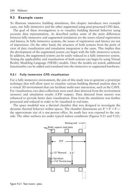
- Page 250 and 251: Figure 9.22 Test room—section. Wa
- Page 252 and 253: (a) (b) Immersive building simulati
- Page 254 and 255: Immersive building simulation 239 m
- Page 256 and 257: Calibrated tracker data Figure 9.30
- Page 258 and 259: Immersive building simulation 243 g
- Page 260 and 261: Immersive building simulation 245 H
- Page 262 and 263: Epilogue Godfried Augenbroe and Ali
- Page 264 and 265: Index accountability 13 accreditati
- Page 266 and 267: performance assessment methods 109-