OPTIPULS 350 i (AIR) OPTIPULS 380 i W
OPTIPULS 350 i (AIR) OPTIPULS 380 i W
OPTIPULS 350 i (AIR) OPTIPULS 380 i W
- No tags were found...

You also want an ePaper? Increase the reach of your titles
YUMPU automatically turns print PDFs into web optimized ePapers that Google loves.
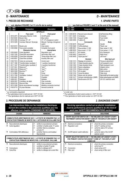
D - MAINTENANCE D - MAINTENANCE1. PIECES DE RECHANGE 1. SPARE PARTS( voir dépliant FIGURE 2 et 11 à la fin de la notice) (see fold-out FIGURE 2 and 11 at the end of the manual)Rep. / REF.Item / REF. Désignation DescriptionRep. / REF.Item / REF. Désignation Description<strong>OPTIPULS</strong> IFace avant Front panel 36 0036 6016 Raccord auto-obturant Self-blocking fitting4 0016 2073 Interrupteur Marche / Arrêt On/Off switch 37 0011 2025 Contacteur Contactor5 0023 6020 Bouton bleu Blue button 38 0020 1030 Support fusible Fuse holder7 0016 3029 Inverseur 2T / 4T 2T / 4T changeover switch 39 0020 0050 Fusible 2A 2A fuse8 0016 3029 Inverseur Manuel / Synergie Manual / Synergy changeover Carrosserie Bodyswitch 40 9160 8470 Brancard * Handle9 0023 6015 Bouton gris Grey button 41 9160 8460 Coiffe plastique Plastic cap11 9160 8506 Face avant complète Complete front panel 42 4086 9021 Roue arrière ∅ 300 Rear wheel ∅ 300Eléments internes Internal items 43 4086 9022 Roue avant ∅ 125 Front wheel ∅ 12520 9160 8428 Carte régulation Regulation card 9160 8711 Kit visserie Kit of fasteners21 0320 7330 Carte filtre secondaire Secondary filter card 9160 8453 Capot droit * Right hood *22 9160 8259 Carte filtre triphasée Three-phase filter card 9160 8455 Capot gauche * Left hood *23 9160 8527 Carte filtre auxiliaire Auxiliary filter card Dévidoir Wire feed unit24 9160 7815 Carte de commande Control card 9160 1013 Réglage de pression Pressure adjustment25 0017 1082 Transformateur auxiliaire 1 1 auxiliary transformer 9160 1021 Chape équipée gauche Left equipped cover26 0017 1047 Transformateur auxiliaire 2 2 auxiliary transformer 9160 1022 Chape équipée droite Right equipped cover27 9157 3031 Réservoir** Tank** 9160 1020 Pignon adaptateur Adapter pinion27 9000 0342 Réservoir*** Tank*** 9160 1019 Pignon principal Main pinion27 9000 0359 Bouchon*** Cap*** 9161 7014 Kit vis galet Roller screw kit28 9114 0884 Pompe Pump 9160 1018 Corps de platine Plate body29 0010 1536 Ventilateur (moteur) Fan (motor) 9160 7442 Moyeu axe de bobine Reel shaft hub for serial number30 9160 4481 Hélice Propeller 9160 1017 Groupe motoréducteur (GMR) Motor-reducing gear unit (GMR)31 9358 0521 Radiateur Radiator 0036 1025 Electrovanne 24V DC 24V DC solenoid valve32 0036 2007 Contrôleur de débit Flow controller33 0036 6100 Raccord filtre Filter connector34 0015 3036 Borne raccordement soudage Welding connection terminal35 9160 8710 Kit prise faisceau Harness socket kit* sur commande uniquement * on order only** Pour générateurs dont le matricule est < 5377 VO 332 ** Pour générators of which serial number is < 5377 VO 332*** Pour générateurs dont le matricule est ≥ 5377 VO 332 *** Pour générators of which serial number is ≥ 5377 VO 3322. PROCEDURE DE DEPANNAGE 2. DIAGNOSIS CHARTLes interventions faites sur les installations électriquesdoivent être confiées à des personnes qualifiées pour leseffectuer (voir chapitre CONSIGNES DE SECURITE).Servicing operations carried out on electric installationsmust be performed by persons qualified to do this kind ofwork (see SAFETY RECOMMENDATIONS section).CAUSES REMEDES CAUSES SOLUTIONSCOMMUTATEUR ARRET/MARCHE SUR 1 / LE POSTE NE DEMARRE PAS / LECONTACTEUR PRIM<strong>AIR</strong>E NE MONTE PAS / L'AFFICHEUR NE S'ALLUME PAS Raccordements électriques Carte régulation Commutateur M/A défectueux vérifier le raccordement primaire contrôler le fusible poste F1 poste contrôler l'état du contacteurprimaire K1 contrôler l'état du commutateurMarche/ArrêtCOMMUTATEUR ARRET/MARCHE SUR 1 / LE POSTE NE DEMARRE PAS / LECONTACTEUR PRIM<strong>AIR</strong>E NE MONTE PAS / L'AFFICHEUR S'ALLUME Raccordements électriques Connecteurs Carte filtre vérifier le raccordement primaire contrôler le fusible F2 poste vérifier le câblage de K1 vérifier le câblage de la carte filtreON/OFF SELECTOR SWITCH ON 1 / THE WELDING SET DOESN’T START /THE PRIMARY CONTACTOR DOESN’T COME UP / THE DISPLAY-UNIT DOESN’TCOME ON Electrical connections Regulation card On/Off selector switch defective check the primary connection verify F1 welding set fuse verify the state of K1 primarycontactor verify the state of the On/Offselector switchON/OFF SELECTOR SWITCH ON 1 / THE WELDING SET DOESN’T START /THE PRIMARY CONTACTOR DOESN’T COME UP / THE DISPLAY-UNITCOMES ON Electrical connections Connectors Filter card check the primary connection verify fuse F2 check wiring of K1 check wiring of filter cardD - 20 <strong>OPTIPULS</strong> <strong>350</strong> I / <strong>OPTIPULS</strong> <strong>380</strong> I W