Bedienungsanleitung / Operation manual 30 MHz Digital ...
Bedienungsanleitung / Operation manual 30 MHz Digital ...
Bedienungsanleitung / Operation manual 30 MHz Digital ...

Erfolgreiche ePaper selbst erstellen
Machen Sie aus Ihren PDF Publikationen ein blätterbares Flipbook mit unserer einzigartigen Google optimierten e-Paper Software.
The description of the Channel Menu is shown as the following list:<br />
Function Menu Setting Description<br />
Coupling<br />
DC<br />
AC<br />
GROUND<br />
Unblock the AC and DC components in the input signal.<br />
Block the DC component in the input signal.<br />
The Input signal is interrupted.<br />
Inverted<br />
OFF The waveform is displayed normally.<br />
ON<br />
Initiate the waveform inverted function.<br />
1X<br />
Probe<br />
10X Choose one according to the probe attenuation factor to<br />
100X make the vertical scale reading accurate.<br />
1000X<br />
11.2. Setting Channel Coupling<br />
Taking the Channel 1 for example, the measured signal is a square wave signal containing the direct current<br />
bias. The operation steps are shown as below:<br />
* Press the CH1 MENU button and call out the CH1 SETUP menu.<br />
* Press the H1 button, the Coupling menu will display at the screen.<br />
* Press the F1 button to select the Coupling item as “DC”. By setting the channel coupling as DC mode, both<br />
DC and AC components of the signal will be passed.<br />
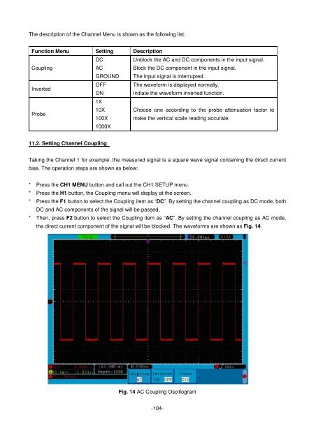
* Then, press F2 button to select the Coupling item as “AC”. By setting the channel coupling as AC mode,<br />
the direct current component of the signal will be blocked. The waveforms are shown as Fig. 14.<br />
Fig. 14 AC Coupling Oscillogram<br />
-104-