Bedienungsanleitung / Operation manual 30 MHz Digital ...
Bedienungsanleitung / Operation manual 30 MHz Digital ...
Bedienungsanleitung / Operation manual 30 MHz Digital ...

Sie wollen auch ein ePaper? Erhöhen Sie die Reichweite Ihrer Titel.
YUMPU macht aus Druck-PDFs automatisch weboptimierte ePaper, die Google liebt.
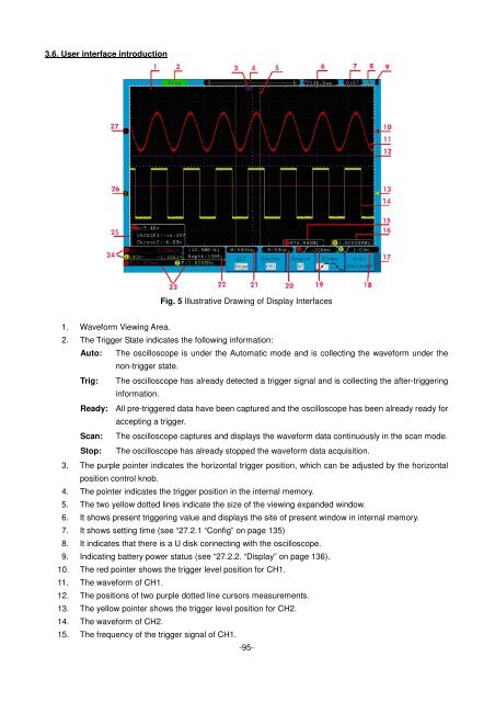
3.6. User interface introduction<br />
Fig. 5 Illustrative Drawing of Display Interfaces<br />
1. Waveform Viewing Area.<br />
2. The Trigger State indicates the following information:<br />
Auto: The oscilloscope is under the Automatic mode and is collecting the waveform under the<br />
non-trigger state.<br />
Trig: The oscilloscope has already detected a trigger signal and is collecting the after-triggering<br />
information.<br />
Ready: All pre-triggered data have been captured and the oscilloscope has been already ready for<br />
accepting a trigger.<br />
Scan: The oscilloscope captures and displays the waveform data continuously in the scan mode.<br />
Stop: The oscilloscope has already stopped the waveform data acquisition.<br />
3. The purple pointer indicates the horizontal trigger position, which can be adjusted by the horizontal<br />
position control knob.<br />
4. The pointer indicates the trigger position in the internal memory.<br />
5. The two yellow dotted lines indicate the size of the viewing expanded window.<br />
6. It shows present triggering value and displays the site of present window in internal memory.<br />
7. It shows setting time (see “27.2.1 “Config” on page 135)<br />
8. It indicates that there is a U disk connecting with the oscilloscope.<br />
9. Indicating battery power status (see “27.2.2. “Display” on page 136).<br />
10. The red pointer shows the trigger level position for CH1.<br />
11. The waveform of CH1.<br />
12. The positions of two purple dotted line cursors measurements.<br />
13. The yellow pointer shows the trigger level position for CH2.<br />
14. The waveform of CH2.<br />
15. The frequency of the trigger signal of CH1.<br />
-95-