Bedienungsanleitung / Operation manual 30 MHz Digital ...
Bedienungsanleitung / Operation manual 30 MHz Digital ...
Bedienungsanleitung / Operation manual 30 MHz Digital ...
Erfolgreiche ePaper selbst erstellen
Machen Sie aus Ihren PDF Publikationen ein blätterbares Flipbook mit unserer einzigartigen Google optimierten e-Paper Software.
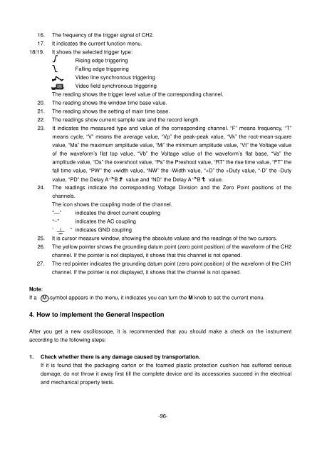
16. The frequency of the trigger signal of CH2.<br />
17. It indicates the current function menu.<br />
18/19. It shows the selected trigger type:<br />
Rising edge triggering<br />
Falling edge triggering<br />
Video line synchronous triggering<br />
Video field synchronous triggering<br />
The reading shows the trigger level value of the corresponding channel.<br />
20. The reading shows the window time base value.<br />
21. The reading shows the setting of main time base.<br />
22. The readings show current sample rate and the record length.<br />
23. It indicates the measured type and value of the corresponding channel. “F” means frequency, “T”<br />
means cycle, “V” means the average value, “Vp” the peak-peak value, “Vk” the root-mean-square<br />
value, “Ma” the maximum amplitude value, “Mi” the minimum amplitude value, “Vt” the Voltage value<br />
of the waveform’s flat top value, “Vb” the Voltage value of the waveform’s flat base, “Va” the<br />
amplitude value, “Os” the overshoot value, “Ps” the Preshoot value, “RT” the rise time value, “FT” the<br />
fall time value, “PW” the +width value, “NW” the -Width value, “+D” the +Duty value, “-D” the -Duty<br />
value, “PD” the Delay A B value and “ND” the Delay A B value.<br />
24. The readings indicate the corresponding Voltage Division and the Zero Point positions of the<br />
channels.<br />
The icon shows the coupling mode of the channel.<br />
“—” indicates the direct current coupling<br />
“~” indicates the AC coupling<br />
“ ” indicates GND coupling<br />
25. It is cursor measure window, showing the absolute values and the readings of the two cursors.<br />
26. The yellow pointer shows the grounding datum point (zero point position) of the waveform of the CH2<br />
channel. If the pointer is not displayed, it shows that this channel is not opened.<br />
27. The red pointer indicates the grounding datum point (zero point position) of the waveform of the CH1<br />
channel. If the pointer is not displayed, it shows that the channel is not opened.<br />
Note:<br />
If a M -symbol appears in the menu, it indicates you can turn the M knob to set the current menu.<br />
4. How to implement the General Inspection<br />
After you get a new oscilloscope, it is recommended that you should make a check on the instrument<br />
according to the following steps:<br />
1. Check whether there is any damage caused by transportation.<br />
If it is found that the packaging carton or the foamed plastic protection cushion has suffered serious<br />
damage, do not throw it away first till the complete device and its accessories succeed in the electrical<br />
and mechanical property tests.<br />
-96-


