Qualification of the Assembly Process of Flip-Chip BGA Packages ...
Qualification of the Assembly Process of Flip-Chip BGA Packages ...
Qualification of the Assembly Process of Flip-Chip BGA Packages ...

Create successful ePaper yourself
Turn your PDF publications into a flip-book with our unique Google optimized e-Paper software.
Texas Tech University, Nivetha Shivan, May 2012<br />
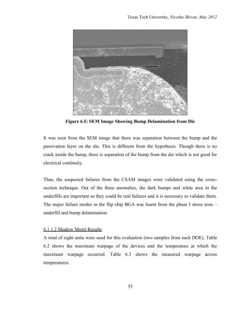
Figure 6.5: SEM Image Showing Bump Delamination from Die<br />
It was seen from <strong>the</strong> SEM image that <strong>the</strong>re was separation between <strong>the</strong> bump and <strong>the</strong><br />
passivation layer on <strong>the</strong> die. This is different from <strong>the</strong> hypo<strong>the</strong>sis. Though <strong>the</strong>re is no<br />
crack inside <strong>the</strong> bump, <strong>the</strong>re is separation <strong>of</strong> <strong>the</strong> bump from <strong>the</strong> die which is not good for<br />
electrical continuity.<br />
Thus, <strong>the</strong> suspected failures from <strong>the</strong> CSAM images were validated using <strong>the</strong> cross-<br />
section technique. Out <strong>of</strong> <strong>the</strong> three anomalies, <strong>the</strong> dark bumps and white area in <strong>the</strong><br />
underfills are important as <strong>the</strong>y could be real failures and it is necessary to validate <strong>the</strong>m.<br />
The major failure modes in <strong>the</strong> flip chip <strong>BGA</strong> was learnt from <strong>the</strong> phase I stress tests –<br />
underfill and bump delamination.<br />
6.1.1.2 Shadow Moiré Results<br />
A total <strong>of</strong> eight units were used for this evaluation (two samples from each DOE). Table<br />
6.2 shows <strong>the</strong> maximum warpage <strong>of</strong> <strong>the</strong> devices and <strong>the</strong> temperature at which <strong>the</strong><br />
maximum warpage occurred. Table 6.3 shows <strong>the</strong> measured warpage across<br />
temperatures.<br />
55