The Locomotive - Lighthouse Survival Blog
The Locomotive - Lighthouse Survival Blog
The Locomotive - Lighthouse Survival Blog

You also want an ePaper? Increase the reach of your titles
YUMPU automatically turns print PDFs into web optimized ePapers that Google loves.
138 THE LOCOMOTIVE, [September,<br />
added to 19.1 gives 19.7, which is the number of Vjraces that would be required if 100<br />
lbs. were the allowable pressure. For a boiler on which only 75 lbs. are allowed, -j^/^ of<br />
this number of braces will be sufficient,— that is, ^Vo (o^" three-quarters) of 19.7, which<br />
is 14.8. Hence 15 braces will be sufficient on a boiler of this size and design, running<br />
at a pressure not exceeding 75 lbs. to the square inch.<br />
When the proper number of braces is known, the next step is to distribute them as<br />
equably as possible over the area to be stayed (i. e., the segment shown by the dotted<br />
lines in Fig. 7). As the arrangement will vary with the number of braces, it will not<br />
be possible to give any general rule for it, except the one above,— namely, to cover the<br />
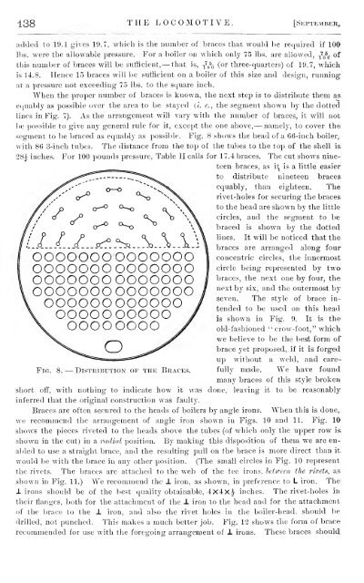
segment to be braced as equably as possible. Fig. 8 shows the head of a 66-inch boiler,<br />
with 86 3-inch tubes. <strong>The</strong> distance from the top of the tubes to the top of the shell is.<br />
28|^ inches. For 100 pounds pressure, Table II calls for 17.4 braces. <strong>The</strong> cut shows nine-<br />
Fig. 8. — Distribution of the Braces.<br />
short off, with nothing to indicate how it was<br />
inferred that the original construction was faulty.<br />
teen braces, as i1^ is a little easier<br />
to distribute nineteen bracesequably,<br />
than eighteen. <strong>The</strong><br />
rivet-holes for securing the braces<br />
to the head are shown by the little<br />
circles, and the segment to be<br />
braced is shown by the dotted<br />
lines. It will be noticed that the<br />
braces are arranged along four<br />
concentric circles, the innermost<br />
circle being represented by twa<br />
braces, the next one by four, the<br />
next by six, and the outermost by<br />
seven. <strong>The</strong> style of brace in-<br />
tended to be used on this head<br />
is shown in Fig. 9. It is the<br />
old-fashioned " crow-foot," which<br />
we believe to be the best form of<br />
brace yet proposed, if it is forged<br />
up without a weld, and carefully<br />
made. We have found<br />
many braces of this style broken<br />
done, leaving it to be reasonably<br />
Braces are often secured to the heads of boilers by angle irons. When this is done,<br />
we recommend the arrangement of angle iron shown in Figs. 10 and 11. Fig. 10<br />
shows the pieces riveted to the heads above the tubes (of which only the upper row is<br />
shown in the cut) in a radial position. By making this disposition of them we are en-<br />
abled to use a straight brace, and the resulting pull on the brace is more direct than it<br />
would be with the brace in any other position. (<strong>The</strong> small circles in Fig. 10 represent<br />
the rivets. <strong>The</strong> braces are attached to the web of the tee irons, letween the rivets, as<br />
shown in Fig. 11.) We recommend the J. iron, as shown, in preference to L iron. <strong>The</strong><br />
± irons should be of the best quality obtainable, 4x4x|^ inches. <strong>The</strong> rivet-holes in<br />
their flanges, both for the attachment of the J. iron to the head and for the attachment<br />
of the brace to the ± iron, and also the rivet holes in the boiler-head, should be<br />
drilled, not punched. This makes a much better job. Fig. 12 shows the form of brace<br />
recommended for use with the foregoing arrangement of ± irons. <strong>The</strong>se braces should