The Locomotive - Lighthouse Survival Blog
The Locomotive - Lighthouse Survival Blog
The Locomotive - Lighthouse Survival Blog

Create successful ePaper yourself
Turn your PDF publications into a flip-book with our unique Google optimized e-Paper software.
34 THE LOCOMOTIVE, [March,<br />
pressure of the fulcrum against the lever. (It is plain that although the lever presses<br />
7/jrwanl against the pin, the pin presses dowmcnrd against the lever.) Now since the<br />
lever does not tip either v;ay, but remains in equilibrium, it must be that the tipping<br />
effect of the weights is just balanced by the opposite tipping effect of the downward<br />
pressure of P against the lever. Now the tipping effect, or moment, of any force is<br />
proportional to the magnitude of the force, and also to the leverage it has. Thus to<br />
find the tendency of the weight A to turn the lever about the point Fas a center, we<br />
multiply 124 by 46;^ (46^ being the distance of this weight from V), which gives 5,735.<br />
This means that the weight A exerts precisely the same tipping effect that a weight of<br />
5, 735 pounds would exert, if hung on the lever at a distance of one inch from V. <strong>The</strong><br />
distances of B and C from V being 37| in. and 30:^ in., respectively, we find that<br />
their respective tipping effects are 37^ x 45 and 30^ x 45, or 1,076^ and 1,361^; so that<br />
A'^m<br />
« •// ><br />
C U<br />
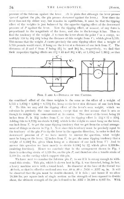
Figs. 3 and 4.—Details op the Casting.<br />
the combined effect of the three weights is the same as the effect of a weight of<br />
5,735 + 1,676| + l,361j = 8,773|^ lbs. hung on the lever at a distance of one inch from<br />
V. To this we may add the tipping effect of the lever's own weight, which we<br />
calculate in precisely the same manner, except that we first assume that it acts as<br />
though its weight were concentrated at its center. <strong>The</strong> center of the lever, being 25<br />
inches from P, is 22| inches from F, so that its tipping effect is 22^ X 17 = 3785^.<br />
Adding this to 8,772|^ we obtain 9, 150|, which is the weight we must hang on the lever,<br />
one inch from F, to get the same tipping tendency that we get from the actual arrangement<br />
of things as shown in Fig. 1. Now since this tendency must be precisely equal to<br />
the tendency of the pin P to tip the lever in the opposite direction, in order to find the<br />
downward pressure of P we have merely to answer the question, what weight<br />
must be hung on the lever, 2| inches from F, to get the same tipping tendency that a<br />
weight of 9,150| lbs. gives when hung at a distance of one inch from F? And to<br />
answer this question we have merely to divide 9,150| by 2|, which gives 3, 328 lbs.<br />
(omitting fractions). Hence we conclude that in the arrangement shown in Fig. 1<br />
there is a shearing strain of 3, 328 lbs. on the pin P, and therefore also a tensile strain of<br />
3,328 lbs. on the casting which sujoport this pin.<br />
We have next to examine the fulcrum pin P, to see if it is strong enough to withstand<br />
this strain. This pin, which is shown best in Fig. 3, was threaded, being, in fact,<br />
a heavy machine screw with a round head. Its diameter at the base of the thread was<br />
.40 inch, so thatits effective sectional area was .40 x .40 x .7854 = .1357 sq. in. It will<br />
be observed that the pin must be double-sheared, if it fails ; and hence if we allow<br />
70,300 lbs. per square inch of single section as the strength of iron exposed to double<br />
shear, the ultimate strength of the pin is found to be .1257 x 70,300 = 8,837 lbs. With