

mitac 8599.pdf - tim.id.au
mitac 8599.pdf - tim.id.au
mitac 8599.pdf - tim.id.au

Create successful ePaper yourself
Turn your PDF publications into a flip-book with our unique Google optimized e-Paper software.
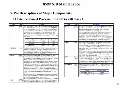
8599 N/B Maintenance<br />
5. Pin Descriptions of Major Components<br />
5.1 Intel Pentium 4 Processor mFC-PGA 478 Pins - 1<br />
Name Type Description<br />
AP[1:0]# Input/<br />
Output<br />
AP[1:0]# (Address Parity) are driven by the request initiator along<br />
with ADS#,A[35:3]#, and the transaction type on the REQ[4:0]#. A<br />
correct parity signal is high if an even number of covered signals<br />
are low and low if an odd number of covered signals are low. This<br />
allows parity to be high when all the covered signals are high.<br />
AP[1:0]# should connect the appropriate pins of all Pentium 4<br />
processor in the 478-pin package system bus agents. The following<br />
table defines<br />
Request Signals subphase 1 subphase 2<br />
A[35:24]# AP0# AP1#<br />
A[23:3]# AP1# AP0#<br />
REQ[4:0]# AP1# AP0#<br />
BCLK[1:0] Input The differential pair BCLK (Bus Clock) determines the system bus<br />
frequency. All processor system bus agents must receive these<br />
signals to drive their outputs and latch their inputs.<br />
All external <strong>tim</strong>ing parameters are specified with respect to the<br />
BINIT# Input/<br />
Output<br />
BNR#<br />
Input/<br />
Output<br />
rising edge of BCLK0 crossing V CROSS .<br />
BINIT# (Bus Initialization) may be observed and driven by all<br />
processor system bus agents and if used, must connect the<br />
appropriate pins of all such agents. If the BINIT# driver is enabled<br />
during power-on configuration, BINIT# is asserted<br />
to signal any bus condition that prevents reliable future operation.<br />
If BINIT# observation is enabled during power-on configuration,<br />
and BINIT# is sampled asserted, symmetric agents reset their bus<br />
LOCK# activity and bus request arbitration state machines. The bus<br />
agents do not reset their IOQ and transaction tracking state<br />
machines upon observation of BINIT# activation. Once the BINIT#<br />
assertion has been observed, the bus agents will re-arbitrate for the<br />
system bus and attempt completion of their bus queue and IOQ<br />
entries.<br />
If BINIT# observation is disabled during power-on configuration, a<br />
central agent may handle an assertion of BINIT# as appropriate to<br />
the error handling architecture of the system.<br />
BNR# (Block Next Request) is used to assert a bus stall by any bus<br />
agent who is unable to accept new bus transactions. During a bus<br />
stall, the current bus owner cannot issue any new transactions.<br />
Name Type Description<br />
A[35:3]# Input/<br />
Output<br />
A[35:3]# (Address) define a 2 36 -byte physical memory address<br />
space. In sub-phase 1 of the address phase, these pins transmit the<br />
address of a transaction. In sub-phase 2, these pins transmit<br />
transaction type information. These signals<br />
must connect the appropriate pins of all agents on the Pentium 4<br />
processor in the 478-pin package system bus. A[35:3]# are<br />
protected by parity signals AP[1:0]#. A[35:3]# are source<br />
synchronous signals and are latched into the receiving buffers by<br />
ADSTB[1:0]#. On the active-to-inactive transition of RESET#, the<br />
processor samples a subset of the A[35:3]# pins to determine<br />
power-on configuration. See Section 7.1 for more details.<br />
A20M# Input If A20M# (Address-20 Mask) is asserted, the processor masks<br />
physical address bit 20 (A20#) before looking up a line in any<br />
internal cache and before driving a read/write transaction on the<br />
bus. Asserting A20M# emulates the 8086 processor's address<br />
wrap-around at the 1-Mbyte boundary. Assertion of A20M# is only<br />
supported in real mode.<br />
A20M# is an asynchronous signal. However, to ensure recognition<br />
of this signal following an Input/Output write instruction, it must be<br />
val<strong>id</strong> along with the TRDY# assertion of the corresponding<br />
ADS# Input/<br />
Output<br />
ADSTB[1:0]# Input/<br />
Output<br />
Input/Output Write bus transaction.<br />
ADS# (Address Strobe) is asserted to indicate the val<strong>id</strong>ity of the<br />
transaction address on the A[35:3]# and REQ[4:0]# pins. All bus<br />
agents observe the ADS# activation to begin parity checking,<br />
protocol checking, address decode, internal snoop, or deferred reply<br />
ID match operations associated with the new transaction.<br />
Address strobes are used to latch A[35:3]# and REQ[4:0]# on their<br />
rising and falling edges. Strobes are associated with signals as<br />
shown below.<br />
Signals Associated Strobe<br />
REQ[4:0]#, A[16:3]# ADSTB0#<br />
A[35:17]# ADSTB1#<br />
73


