

mitac 8599.pdf - tim.id.au
mitac 8599.pdf - tim.id.au
mitac 8599.pdf - tim.id.au

You also want an ePaper? Increase the reach of your titles
YUMPU automatically turns print PDFs into web optimized ePapers that Google loves.
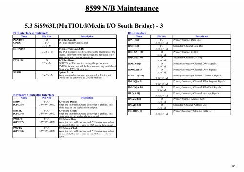
8599 N/B Maintenance<br />
5.3 SiS963L(MuTIOL®Media I/O South Br<strong>id</strong>ge) - 3<br />
PCI Interface (Continued)<br />
Name Pin Attr Description<br />
PGNT5# /<br />
GPIO6<br />
O<br />
I/O<br />
3.3V- M<br />
INT[A:D]# I<br />
3.3V/5V –M<br />
PCIRST# O<br />
3.3V –M<br />
SERR# I<br />
3.3V/5V –M<br />
PCI Bus Grant:<br />
PCI Bus Master Grant Signal<br />
PCI interrupt A,B,C,D:<br />
The PCI interrupts will be connected to the inputs of the<br />
internal Interrupt controller through the rerouting logic<br />
associated with each PCI interrupt.<br />
PCI Bus Reset:<br />
PCIRST# will be asserted during the period when<br />
PWROK is low, and will be kept on asserting until about<br />
24ms after PWROK goes high.<br />
System Error:<br />
When sampled active low, a non-maskable interrupt<br />
(NMI) can be generated to CPU if enabled.<br />
Keyboard Controller Interface<br />
Name Pin Attr Description<br />
KBDAT<br />
(GPIO15)<br />
KBCLK<br />
(GPIO16)<br />
PMDAT<br />
(GPIO17)<br />
PMCLK<br />
(GPIO18)<br />
I/OD<br />
3.3V/5V -AUX<br />
I/OD<br />
3.3V/5V -AUX<br />
I/OD<br />
3.3V/5V -AUX<br />
I/OD<br />
3.3V/5V -AUX<br />
Keyboard Dada:<br />
When the internal keyboard controller is enabled, this<br />
pin is used as the keyboard data signal.<br />
Keyboard Clock:<br />
When the internal keyboard controller is enabled, this<br />
pin is used as the keyboard clock signal.<br />
PS2 Mouse Data:<br />
When the internal keyboard and PS2 mouse controllers<br />
are enabled, this pin is used as PS2 mouse data signal.<br />
PS2 Mouse Clock:<br />
When the internal keyboard and PS2 mouse controllers<br />
are enabled, this pin is used as the PS2 mouse clock<br />
signal.<br />
IDE Interface<br />
Name Pin Attr Description<br />
IDA[15:0] I/O<br />
3.3V/5V -M<br />
IDB[15:0] I/O<br />
3.3V/5V -M<br />
IDECSA[1:0]# O<br />
3.3V -M<br />
IDECSB[1:0]# O<br />
3.3V -M<br />
IIOR[A:B]# O<br />
3.3V -M<br />
IIOW[A:B]# O<br />
3.3V -M<br />
ICHRDY[A:B] I<br />
3.3V/5V -M<br />
IDREQ[A:B] I<br />
3.3V/5V -M<br />
IDACK[A:B]# O<br />
3.3V -M<br />
IIRQ[A:B] I<br />
3.3V/5V -M<br />
IDSAA[2:0] O<br />
3.3V -M<br />
IDSAB[2:0] O<br />
3.3V -M<br />
CBLID[A:B] I<br />
3.3V/5V -M<br />
Primary Channel Data Bus<br />
Secondary Channel Data Bus<br />
Primary Channel CS[1:0]<br />
Secondary Channel CS[1:0]<br />
Primary/Secondary Channel IOR# Signals<br />
Primary/Secondary Channel IOW# Signals<br />
Primary/Secondary Channel ICHRDY# Signals<br />
Primary/Secondary Channel DMA Request Signals<br />
Primary/Secondary Channel DMACK# Signals<br />
Primary/Secondary Channel Interrupt Signals<br />
Primary Channel Address [2:0]<br />
Secondary Channel Address [2:0]<br />
Primary/Secondary Ultra-66 Cable ID<br />
85


