

mitac 8599.pdf - tim.id.au
mitac 8599.pdf - tim.id.au
mitac 8599.pdf - tim.id.au

Create successful ePaper yourself
Turn your PDF publications into a flip-book with our unique Google optimized e-Paper software.
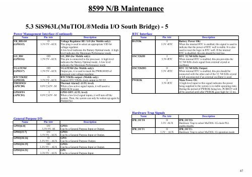
8599 N/B Maintenance<br />
5.3 SiS963L(MuTIOL®Media I/O South Br<strong>id</strong>ge) - 5<br />
Power Management Interface (Continued)<br />
Name Pin Attr Description<br />
VR_HILO#<br />
(GPIO15)<br />
LO_HI#<br />
(GPIO16)<br />
VGATEM#<br />
(GPIO17)<br />
RTC32KHZ<br />
(GPIO18)<br />
THERM2#<br />
(APICD0)<br />
GPIOFF#<br />
(APICD1)<br />
O<br />
3.3V/5V -AUX<br />
OD<br />
1.5V/5V -AUX<br />
OD<br />
1.5V/5V -AUX<br />
O<br />
3.3V/5V -AUX<br />
I<br />
0.8V/2.65V -M<br />
I<br />
0.8V/2.65V -M<br />
Voltage Regulator HI / LO (for Mobile only):<br />
This ping is used to select an appropriate VID for<br />
voltage regulator.<br />
A low level indicates the Battery Op<strong>tim</strong>al mode. A high<br />
level indicates the Maximum Performance mode.<br />
LO_HI# (for Mobile only):<br />
This pin is connected to the processor. A high level<br />
indicates the Battery Op<strong>tim</strong>al mode. A low level<br />
indicates the Maximum Performance mode.<br />
VGATEM# (for Mobile only):<br />
Output pin, it is used to mask the PWRGOOD of<br />
processor core voltage regulator.<br />
RTC32KHz output: (Mobile only)<br />
Support RTC32KHz clock output in S0~S5.<br />
Thermal Alarm2: (GTL level)<br />
When a low active signal inputs, it will assert a<br />
SMI#/SCI# event.<br />
GPIO OFF: (GTL level)<br />
When a low level signal inputs, it will turn off the<br />
system. Then, the system can only be woken up again by<br />
PWRBTN#.<br />
General Purpose I/O<br />
Name Pin Attr Description<br />
GPIO[6:0] I/O<br />
3.3V/5V -M<br />
GPIO[15:7] I/O<br />
3.3V/5V - AUX<br />
GPIO[18:16] O<br />
3.3V/5V – AUX<br />
GPIO[20:19] OD<br />
3.3V/5V – AUX<br />
GPIO[24:21] I<br />
3.3V/5V - AUX<br />
GPIO:<br />
Can be a General Purpose Input or Output.<br />
GPIO:<br />
Can be a General Purpose Input or Output.<br />
GPO:<br />
Can be a General Purpose Output.<br />
GPIO:<br />
Can be a General Purpose Input or Output.<br />
GPI:<br />
Can be a General Purpose Input.<br />
RTC Interface<br />
Name Pin Attr Description<br />
BATOK I<br />
3.3V -RTC<br />
OSC32KHI I<br />
3.3V-RTC<br />
OSC32KHO O<br />
3.3V -RTC<br />
PWROK I<br />
3.3V-RTC<br />
Battery Power OK:<br />
When the internal RTC is enabled, this signal is used to<br />
indicate that the power of RTC well is stable. It is also<br />
used to reset the logic in RTC well. If the internal<br />
RTC is disabled, this pin should be tied low.<br />
RTC 32.768 KHz Input:<br />
When internal RTC is enabled, this pin prov<strong>id</strong>es the<br />
32.768 KHz clock signal from external crystal or<br />
oscillator.<br />
RTC 32.768 KHz Output:<br />
When internal RTC is enabled, this pin should be<br />
connected with the other end of the 32.768 KHz crystal<br />
or left unconnected if an external oscillator is used.<br />
Main Power OK:<br />
A high-level input to this signal indicates the power<br />
being supplied to the system is in stable operating state.<br />
During the period of PWROK being low, PCIRST# will<br />
all be asserted until after PWROK goes high for 12 ms.<br />
Hardware Trap Signals<br />
Name Pin Attr Description<br />
IPB_OUT0 O<br />
3.3V -AUX<br />
IPB_OUT1 O<br />
3.3V – AUX<br />
IPB_OUTO:<br />
Hardware Trap to select MuTIOL 1G clock PLL<br />
enable/disable<br />
IPB_OUT1:<br />
Hardware Trap to select MuTIOL 1G operation mode<br />
87


