

mitac 8599.pdf - tim.id.au
mitac 8599.pdf - tim.id.au
mitac 8599.pdf - tim.id.au

You also want an ePaper? Increase the reach of your titles
YUMPU automatically turns print PDFs into web optimized ePapers that Google loves.
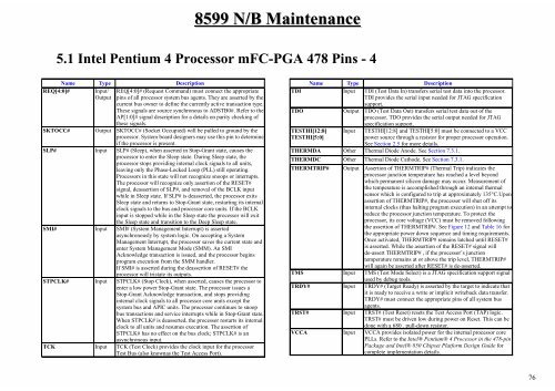
Name Type Description<br />
REQ[4:0]# Input/ REQ[4:0]# (Request Command) must connect the appropriate<br />
Output pins of all processor system bus agents. They are asserted by the<br />
current bus owner to define the currently active transaction type.<br />
These signals are source synchronous to ADSTB0#. Refer to the<br />
AP[1:0]# signal description for a details on parity checking of<br />
these signals.<br />
SKTOCC# Output SKTOCC# (Socket Occupied) will be pulled to ground by the<br />
processor. System board designers may use this pin to determine<br />
if the processor is present.<br />
SLP#<br />
Input SLP# (Sleep), when asserted in Stop-Grant state, c<strong>au</strong>ses the<br />
processor to enter the Sleep state. During Sleep state, the<br />
processor stops prov<strong>id</strong>ing internal clock signals to all units,<br />
leaving only the Phase-Locked Loop (PLL) still operating.<br />
Processors in this state will not recognize snoops or interrupts.<br />
The processor will recognize only assertion of the RESET#<br />
signal, deassertion of SLP#, and removal of the BCLK input<br />
while in Sleep state. If SLP# is deasserted, the processor exits<br />
Sleep state and returns to Stop-Grant state, restarting its internal<br />
clock signals to the bus and processor core units. If the BCLK<br />
input is stopped while in the Sleep state the processor will exit<br />
the Sleep state and transition to the Deep Sleep state.<br />
SMI#<br />
Input SMI# (System Management Interrupt) is asserted<br />
asynchronously by system logic. On accepting a System<br />
Management Interrupt, the processor saves the current state and<br />
enter System Management Mode (SMM). An SMI<br />
Acknowledge transaction is issued, and the processor begins<br />
program execution from the SMM handler.<br />
If SMI# is asserted during the deassertion of RESET# the<br />
processor will tristate its outputs.<br />
STPCLK# Input STPCLK# (Stop Clock), when asserted, c<strong>au</strong>ses the processor to<br />
enter a low power Stop-Grant state. The processor issues a<br />
Stop-Grant Acknowledge transaction, and stops prov<strong>id</strong>ing<br />
internal clock signals to all processor core units except the<br />
system bus and APIC units. The processor continues to snoop<br />
bus transactions and service interrupts while in Stop-Grant state.<br />
When STPCLK# is deasserted, the processor restarts its internal<br />
clock to all units and resumes execution. The assertion of<br />
STPCLK# has no effect on the bus clock; STPCLK# is an<br />
asynchronous input.<br />
TCK<br />
Input TCK (Test Clock) prov<strong>id</strong>es the clock input for the processor<br />
Test Bus (also knownas the Test Access Port).<br />
8599 N/B Maintenance<br />
5.1 Intel Pentium 4 Processor mFC-PGA 478 Pins - 4<br />
Name Type Description<br />
TDI<br />
Input TDI (Test Data In) transfers serial test data into the processor.<br />
TDI prov<strong>id</strong>es the serial input needed for JTAG specification<br />
support.<br />
TDO<br />
Output TDO (Test Data Out) transfers serial test data out of the<br />
processor. TDO prov<strong>id</strong>es the serial output needed for JTAG<br />
specification support.<br />
TESTHI[12:8] Input TESTHI[12:8] and TESTHI[5:0] must be connected to a VCC<br />
TESTHI[5:0]<br />
power source through a resistor for proper processor operation.<br />
See Section 2.5 for more details.<br />
THERMDA Other Thermal Diode Anode. See Section 7.3.1.<br />
THERMDC Other Thermal Diode Cathode. See Section 7.3.1.<br />
THERMTRIP#<br />
TMS<br />
TRDY#<br />
TRST#<br />
VCCA<br />
Output<br />
Input<br />
Input<br />
Input<br />
Input<br />
Assertion of THERMTRIP# (Thermal Trip) indicates the<br />
processor junction temperature has reached a level beyond<br />
which permanent silicon damage may occur. Measurement of<br />
the temperature is accomplished through an internal thermal<br />
sensor which is configured to trip at approximately 135°C.Upon<br />
assertion of THERMTRIP#, the processor will shut off its<br />
internal clocks (thus halting program execution) in an attempt to<br />
reduce the processor junction temperature. To protect the<br />
processor, its core voltage (VCC) must be removed following<br />
the assertion of THERMTRIP#. See Figure 12 and Table 16 for<br />
the appropriate power down sequence and <strong>tim</strong>ing requirements.<br />
Once activated, THERMTRIP# remains latched until RESET#<br />
is asserted. While the assertion of the RESET# signal will<br />
de-assert THERMTRIP# , if the processor’s junction<br />
temperature remains at or above the trip level, THERMTRIP#<br />
will again be asserted after RESET# is de-asserted.<br />
TMS (Test Mode Select) is a JTAG specification support signal<br />
used by debug tools.<br />
TRDY# (Target Ready) is asserted by the target to indicate that<br />
it is ready to receive a write or implicit writeback data transfer.<br />
TRDY# must connect the appropriate pins of all system bus<br />
agents.<br />
TRST# (Test Reset) resets the Test Access Port (TAP) logic.<br />
TRST# must be driven low during power on Reset. This can be<br />
done with a 680 . pull-down resistor.<br />
VCCA prov<strong>id</strong>es isolated power for the internal processor core<br />
PLLs. Refer to the Intel® Pentium® 4 Processor in the 478-pin<br />
Package and Intel® 850 Chipset Platform Design Gu<strong>id</strong>e for<br />
complete implementation details.<br />
76


