Training Manual on Energy Efficiency - APO Asian Productivity ...
Training Manual on Energy Efficiency - APO Asian Productivity ...
Training Manual on Energy Efficiency - APO Asian Productivity ...

You also want an ePaper? Increase the reach of your titles
YUMPU automatically turns print PDFs into web optimized ePapers that Google loves.
Water enters the center (eye) of the impeller and exits the impeller with the<br />
help of centrifugal force. As water leaves the eye of the impeller a low-pressure<br />
area is created, causing more water to flow into the eye. Atmospheric pressure<br />
and centrifugal force cause this to happen. Velocity is developed as the water<br />
flows through the impeller, which is spinning at high speed. The water velocity<br />
is collected by the diffuser and c<strong>on</strong>verted to pressure by specially designed<br />
passageways that direct the flow to the discharge of the pump, or to the next<br />
impeller should the pump have a multi-stage c<strong>on</strong>figurati<strong>on</strong>.<br />
The pressure (head) that a pump will develop is in direct relati<strong>on</strong>ship to the<br />
impeller diameter, the number of impellers, the size of the impeller eye, and<br />
the shaft speed. Capacity is determined by the exit width of the impeller. The<br />
head and capacity are the main factors that affect the horsepower size of the<br />
motor to be used. The greater the quantity of water to be pumped, the more<br />
energy is required.<br />
7.3 SYSTEM CHARACTERISTICS<br />
In a pumping system, the objective, in most cases, is either to transfer a liquid<br />
from a source to a required destinati<strong>on</strong> (e.g. filling a high-level reservoir) or<br />
to circulate liquid around a system (e.g. as a means of heat transfer in heat<br />
exchanger).<br />
Head losses<br />
Pressure is needed to make the liquid flow at the required rate, and this<br />
pressure must overcome head “losses” in the system. Losses are of two types:<br />
static head and fricti<strong>on</strong> head.<br />
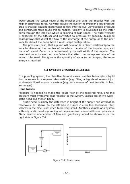
Static head is simply the difference in height of the supply and destinati<strong>on</strong><br />
reservoirs, as shown <strong>on</strong> the left side in Figure 7-2. In this illustrati<strong>on</strong>, flow<br />
velocity in the pipe is assumed to be very small. Another example of a system<br />
with <strong>on</strong>ly static head is pumping into a pressurized vessel with short pipe runs.<br />
Static head is independent of flow and graphically would be shown as <strong>on</strong> the<br />
right side in Figure 7-2.<br />
Figure 7-2 Static head<br />
- 65 -<br />
<strong>Energy</strong> <strong>Efficiency</strong> in Pumps