

User's Manual ISO TNC 360 (260020xx, 280490xx) - heidenhain
User's Manual ISO TNC 360 (260020xx, 280490xx) - heidenhain
User's Manual ISO TNC 360 (260020xx, 280490xx) - heidenhain

You also want an ePaper? Increase the reach of your titles
YUMPU automatically turns print PDFs into web optimized ePapers that Google loves.
8 Cycles<br />
8.3 SL Cycles<br />
8-18<br />
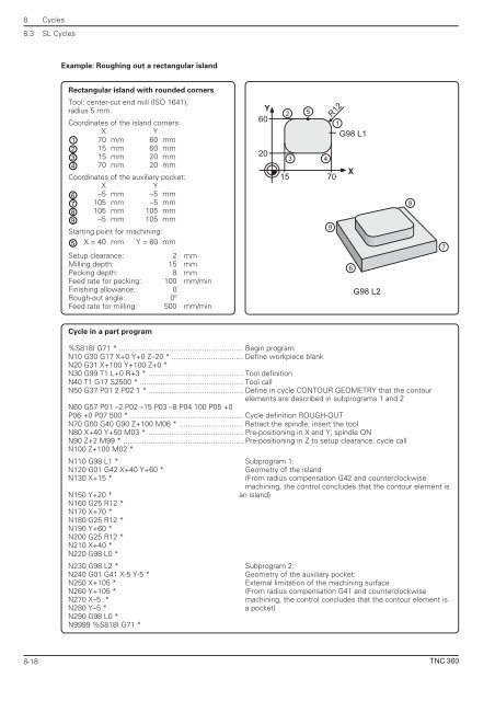
Example: Roughing out a rectangular island<br />
Rectangular island with rounded corners<br />
Tool: center-cut end mill (<strong>ISO</strong> 1641),<br />
radius 5 mm.<br />
Coordinates of the island corners:<br />
X Y<br />
1 70 mm 60 mm<br />
2 15 mm 60 mm<br />
3 15 mm 20 mm<br />
4 70 mm 20 mm<br />
Coordinates of the auxiliary pocket:<br />
X Y<br />
6 –5 mm –5 mm<br />
7 105 mm –5 mm<br />
8 105 mm 105 mm<br />
9 –5 mm 105 mm<br />
Starting point for machining:<br />
5 X = 40 mm Y = 60 mm<br />
Setup clearance: 2 mm<br />
Milling depth: 15 mm<br />
Pecking depth: 8 mm<br />
Feed rate for pecking: 100 mm/min<br />
Finishing allowance: 0<br />
Rough-out angle: 00 Feed rate for milling: 500 mm/min<br />
Cycle in a part program<br />
Y<br />
60<br />
20<br />
15 70<br />
%S818I G71 * ............................................................ Begin program<br />
N10 G30 G17 X+0 Y+0 Z–20 * ................................... Define workpiece blank<br />
N20 G31 X+100 Y+100 Z+0 *<br />
N30 G99 T1 L+0 R+3 * .............................................. Tool definition<br />
N40 T1 G17 S2500 * .................................................. Tool call<br />
N50 G37 P01 2 P02 1 * .............................................. Define in cycle CONTOUR GEOMETRY that the contour<br />
elements are described in subprograms 1 and 2<br />
N60 G57 P01 –2 P02 –15 P03 –8 P04 100 P05 +0<br />
P06 +0 P07 500 * ....................................................... Cycle definition ROUGH-OUT<br />
N70 G00 G40 G90 Z+100 M06 * ............................... Retract the spindle, insert the tool<br />
N80 X+40 Y+50 M03 * .............................................. Pre-positioning in X and Y, spindle ON<br />
N90 Z+2 M99 * .......................................................... Pre-positioning in Z to setup clearance, cycle call<br />
N100 Z+100 M02 *<br />
N110 G98 L1 * Subprogram 1:<br />
N120 G01 G42 X+40 Y+60 * Geometry of the island<br />
N130 X+15 * (From radius compensation G42 and counterclockwise<br />
machining, the control concludes that the contour element is<br />
N150 Y+20 * an island)<br />
N160 G25 R12 *<br />
N170 X+70 *<br />
N180 G25 R12 *<br />
N190 Y+60 *<br />
N200 G25 R12 *<br />
N210 X+40 *<br />
N220 G98 L0 *<br />
N230 G98 L2 * Subprogram 2:<br />
N240 G01 G41 X-5 Y-5 * Geometry of the auxiliary pocket:<br />
N250 X+105 * External limitation of the machining surface<br />
N260 Y+105 * (From radius compensation G41 and counterclockwise<br />
N270 X–5 * machining, the control concludes that the contour element is<br />
N280 Y–5 * a pocket)<br />
N290 G98 L0 *<br />
N9999 %S818I G71 *<br />
2<br />
5<br />
3 4<br />
9<br />
R12<br />
1<br />
G98 L1<br />
X<br />
6<br />
G98 L2<br />
8<br />
7<br />
<strong>TNC</strong> <strong>360</strong>


