

User's Manual ISO TNC 360 (260020xx, 280490xx) - heidenhain
User's Manual ISO TNC 360 (260020xx, 280490xx) - heidenhain
User's Manual ISO TNC 360 (260020xx, 280490xx) - heidenhain

You also want an ePaper? Increase the reach of your titles
YUMPU automatically turns print PDFs into web optimized ePapers that Google loves.
1 Introduction<br />
1.2 Fundamentals of NC<br />
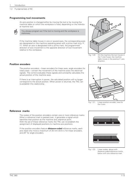
Programming tool movements<br />
An axis position is changed either by moving the tool or by moving the<br />
machine table on which the workpiece is fixed, depending on the individual<br />
machine tool.<br />
You always program as if the tool is moving and the workpiece is<br />
stationary.<br />
If the machine table moves in one or several axes, the corresponding axes<br />
are designated on the machine operating panel with a prime mark (e.g. X’,<br />
Y’). When an axis is designated with a prime mark, the programmed<br />
direction of axis movement is the opposite direction of tool movement<br />
relative to the workpiece.<br />
Position encoders<br />
The position encoders – linear encoders for linear axes, angle encoders for<br />
rotary axes – convert the movement of the machine axes into electrical<br />
signals. The control evaluates these signals and constantly calculates the<br />
actual position of the machine axes.<br />
If there is an interruption in power, the calculated position will no longer<br />
correspond to the actual position. When power is returned, the <strong>TNC</strong> can<br />
re-establish this relationship.<br />
Reference marks<br />
The scales of the position encoders contain one or more reference marks.<br />
When a reference mark is passed over, it generates a signal which<br />
identifies that position as the machine axis reference point.<br />
With the aid of these reference marks the <strong>TNC</strong> can re-establish the<br />
assignment of displayed positions to machine axis positions.<br />
If the position encoders feature distance-coded reference marks, each<br />
axis need only move a maximum of 20 mm (0.8 in.) for linear encoders,<br />
and 20° for angle encoders.<br />
Fig. 1.20: On this machine the tool moves in<br />
the Y and Z axes; the machine<br />
table moves in the positive X' axis<br />
direction.<br />
Fig. 1.21: Linear position encoder, here for<br />
the X axis<br />
Fig. 1.22: Linear scales: above with<br />
distance-coded-reference marks,<br />
below with one reference mark<br />
<strong>TNC</strong> <strong>360</strong> 1-13<br />
+Y<br />
Y<br />
Z<br />
+Z<br />
+X<br />
X


