

User's Manual ISO TNC 360 (260020xx, 280490xx) - heidenhain
User's Manual ISO TNC 360 (260020xx, 280490xx) - heidenhain
User's Manual ISO TNC 360 (260020xx, 280490xx) - heidenhain

Create successful ePaper yourself
Turn your PDF publications into a flip-book with our unique Google optimized e-Paper software.
1 Introduction<br />
1.2 Fundamentals of NC<br />
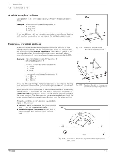
Absolute workpiece positions<br />
Each position on the workpiece is clearly defined by its absolute coordinates.<br />
Example: Absolute coordinates of the position ➀:<br />
X = 20 mm<br />
Y = 10 mm<br />
Z = 15 mm<br />
If you are drilling or milling a workpiece according to a workpiece drawing<br />
with absolute coordinates, you are moving the tool to the coordinates.<br />
Incremental workpiece positions<br />
A position can be referenced to the previous nominal position: i.e. the<br />
relative datum is always the last programmed position. Such coordinates<br />
are referred to as incremental coordinates (increment = growth), or also<br />
incremental or chain dimensions (since the positions are defined as a<br />
chain of dimensions). Incremental coordinates are designated with G91.<br />
Example: Incremental coordinates of the position ➂<br />
referenced to position ➁<br />
Absolute coordinates of the position ➁ :<br />
X = 10 mm<br />
Y = 5 mm<br />
Z = 20 mm<br />
Incremental coordinates of the position ➂ :<br />
IX = 10 mm<br />
IY = 10 mm<br />
IZ = –15 mm<br />
If you are drilling or milling a workpiece according to a workpiece drawing<br />
with incremental coordinates, you are moving the tool by the coordinates.<br />
An incremental position definition is therefore intended as an immediately<br />
relative definition. This is also the case when a position is defined by the<br />
distance-to-go to the target position (here the relative datum is located at<br />
the target position). The distance-to-go has a negative algebraic sign if the<br />
target position lies in the negative axis direction from the actual position.<br />
The polar coordinate system can also express both<br />
types of dimensions:<br />
• Absolute polar coordinates always refer to the<br />
pole I, J and the angle reference axis.<br />
• Incremental polar coordinates always refer to<br />
the last programmed nominal position of the<br />
tool.<br />
Fig. 1.16: Position ➀ of the example<br />
"absolute workpiece positions"<br />
Fig. 1.17: Positions ➁ and ➂ of the example<br />
"incremental workpiece positions"<br />
<strong>TNC</strong> <strong>360</strong> 1-11<br />
Y<br />
Y<br />
10 Z=15mm<br />
Y<br />
10<br />
5<br />
G91R<br />
R<br />
15<br />
20<br />
0<br />
Z<br />
Z<br />
15<br />
G91H G91H<br />
5<br />
1<br />
X=20mm Y=10mm<br />
0<br />
2<br />
3<br />
IZ=–15mm<br />
IY=10mm<br />
IX=10mm<br />
R<br />
H<br />
J = 10 0°<br />
I = 30<br />
Fig. 1.18: Incremental dimensions in polar coordinates (designated<br />
with "G91")<br />
R<br />
10<br />
20<br />
10<br />
X<br />
X<br />
X


