Volume-II - GAIL
Volume-II - GAIL
Volume-II - GAIL
Create successful ePaper yourself
Turn your PDF publications into a flip-book with our unique Google optimized e-Paper software.
6.2.7.3<br />
(New)<br />
6.2.7.4<br />
(New)<br />
Procedure<br />
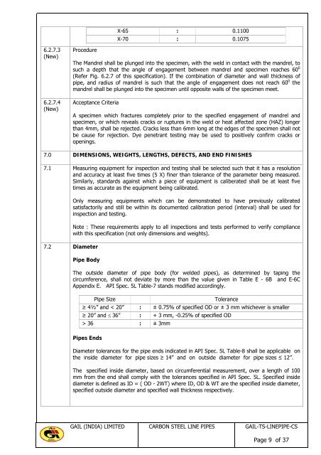
X-65 : 0.1100<br />
X-70 : 0.1075<br />
The Mandrel shall be plunged into the specimen, with the weld in contact with the mandrel, to<br />
such a depth that the angle of engagement between mandrel and specimen reaches 60 0<br />
(Refer Fig. 6.2.7 of this specification). If the combination of diameter and wall thickness of<br />
pipe, and radius of mandrel is such that the angle of engagement does not reach 60 0 the<br />
mandrel shall be plunged into the specimen until opposite walls of the specimen meet.<br />
Acceptance Criteria<br />
A specimen which fractures completely prior to the specified engagement of mandrel and<br />
specimen, or which reveals cracks or ruptures in the weld or heat affected zone (HAZ) longer<br />
than 4mm, shall be rejected. Cracks less than 6mm long at the edges of the specimen shall not<br />
be cause for rejection. Dye penetrant testing may be used to positively confirm cracks or<br />
openings.<br />
7.0 DIMENSIONS, WEIGHTS, LENGTHS, DEFECTS, AND END FINISHES<br />
7.1 Measuring equipment for inspection and testing shall be selected such that it has a resolution<br />
and accuracy at least five times (5 X) finer than tolerance of the parameter being measured.<br />
Similarly, standards against which a piece of equipment is caliberated shall be at least five<br />
times as accurate as the equipment being calibrated.<br />
7.2 Diameter<br />
Only measuring equipments which can be demonstrated to have previously calibrated<br />
satisfactorily and still be within its documented calibration period (interval) shall be used for<br />
inspection and testing.<br />
Note : These requirements apply to all inspections and tests performed to verify compliance<br />
with this specification (not only dimensions and weights).<br />
Pipe Body<br />
The outside diameter of pipe body (for welded pipes), as determined by taping the<br />
circumference, shall not deviate by more than the value given in Table E - 6B and E-6C<br />
Appendix E. API Spec. 5L Table-7 stands modified accordingly.<br />
Pipe Size Tolerance<br />
≥ 4½” and < 20” : ± 0.75% of specified OD or ± 3 mm whichever is smaller<br />
≥ 20” and ≤ 36” : + 3 mm, -0.25% of specified OD<br />
> 36 : ± 3mm<br />
Pipes Ends<br />
Diameter tolerances for the pipe ends indicated in API Spec. 5L Table-8 shall be applicable on<br />
the inside diameter for pipe sizes ≥ 14” and on outside diameter for pipe sizes ≤ 12”.<br />
The specified inside diameter, based on circumferential measurement, over a length of 100<br />
mm from the end shall comply with the tolerances specified in API Spec. 5L. Specified inside<br />
diameter is defined as ID = ( OD - 2WT) where ID, OD & WT are the specified inside diameter,<br />
specified outside diameter and specified wall thickness respectively.<br />
<strong>GAIL</strong> (INDIA) LIMITED CARBON STEEL LINE PIPES <strong>GAIL</strong>-TS-LINEPIPE-CS<br />
Page 9 of 37


