Volume-II - GAIL
Volume-II - GAIL
Volume-II - GAIL

Create successful ePaper yourself
Turn your PDF publications into a flip-book with our unique Google optimized e-Paper software.
APPENDIX - F<br />
SUPPLEMENTARY REQUIREMENTS (NORMATIVE)<br />
SR 5 FRACTURE TOUGHNESS TESTING (CHARPY V - NOTCH) FOR PIPE SIZE 4½” OR<br />
LARGER<br />
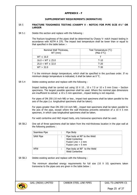
SR 5.1 Delete this section and replace with the following :<br />
The fracture toughness of the pipes shall be determined by Charpy V- notch impact testing in<br />
accordance with ASTM A 370. The impact test temperature shall be lower than or equal to<br />
that specified in the table below :-<br />
Nominal Wall Thickness,<br />
WT (mm)<br />
Test Temperature ( o C)<br />
(Max 0 o C)<br />
WT ≤ 16.0 T<br />
16.0 < WT ≤ 25.0 T-10<br />
25.0 < WT ≤ 32.0 T-20<br />
WT > 32.0 T-30<br />
T is the minimum design temperature, which shall be specified in the purchase order. If no<br />
minimum design temperature is indicated, it shall be taken as 0 o C.<br />
SR 5.4 Delete existing section and replace with the following :<br />
Impact testing shall be carried out using 10 X 10 , 10 x 7.5 or 10 x 5 mm Cross – Section<br />
specimens. The largest possible specimen shall be used. Where the nominal pipe dimensions<br />
are insufficient to extract a 10 x 5 mm specimen , impact testing is not required.<br />
For pipes of DN 250 (10 inch NB) or less , impact test specimens shall be taken parallel to the<br />
axis of the pipe (i.e. longitudinal specimens shall be taken).<br />
For pipes greater than DN 250 (10 inch NB) , impact test specimens shall be taken parallel to<br />
the axis of the pipe, except where the wall thickness prevents extraction of a 10 X 5 mm<br />
specimen, in which case longitudinal specimens shall be taken.<br />
For weld centerline and HAZ impact tests, only transverse specimens shall be used.<br />
SR 5B.2 One set of three specimens shall be taken from the mid-thickness location in the pipe wall at<br />
the following positions :<br />
Seamless Pipe : Pipe Body<br />
SAW Pipe : Pipe body at 90 o to the Weld<br />
Weld Centerline<br />
Fusion Line + 2 mm<br />
Fusion Line + 5 mm<br />
HFW : Pipe body at 90 o to the Weld<br />
Weld Centerline<br />
SR 5B.3 Delete existing section and replace with the following :<br />
The minimum absorbed energy requirements for full size (10 X 10) specimens taken<br />
transverse to the pipes axis are given in the table below :<br />
<strong>GAIL</strong> (INDIA) LIMITED CARBON STEEL LINE PIPES <strong>GAIL</strong>-TS-LINEPIPE-CS<br />
Page 25 of 37