Volume-II - GAIL
Volume-II - GAIL
Volume-II - GAIL

Create successful ePaper yourself
Turn your PDF publications into a flip-book with our unique Google optimized e-Paper software.
performed by automatic equipment over the entire surface of the pipe.<br />
If parts of the ultimate pipe ends are not covered by an automatic EMT system (untested<br />
area), then manual ultrasonic shall be carried out using approved procedures for manual<br />
ultrasonic examination based on the requirements given above. The complete circumference of<br />
the pipe ends shall be tested by manual UT, over the length of the untested area plus 25mm<br />
overlap of the automatically tested area.<br />
9.8.5.2 Ultrasonic and Electromagnetic Inspection Reference Standards<br />
Following will also be noted.<br />
The reference standard (Calibration pipe) shall have the same specified diameter and wall<br />
thickness as the pipe being inspected and shall be of sufficient length to permit calibration of<br />
ultrasonic inspection equipment at the speed to be used in normal production. The reference<br />
standard (calibration pipe) shall also be of the same material, type and have the same surface<br />
finish and heat treatment as the product to be inspected. It shall be free from discontinuities<br />
or other conditions producing indications that may interfere with detection of the reference<br />
reflectors. The reference standard shall contain notches (N5 or N10) or radially drilled holes<br />
(3.2mm).<br />
The Manufacturer may use a type of reference reflector, not specified above, provided he can<br />
demonstrate to Purchaser that the examination is at least as sensitive as prescribed in this<br />
specification. In such cases , the Manufacturer shall obtain approval from Purchaser.<br />
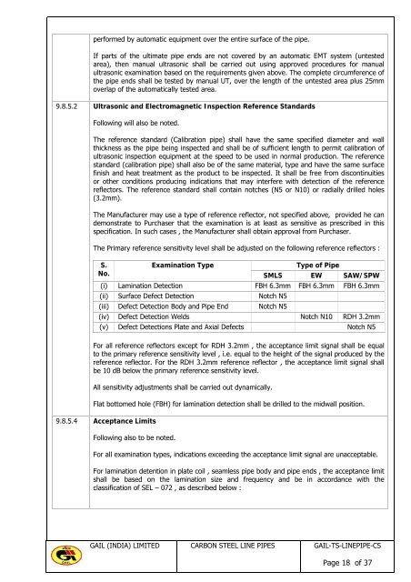
The Primary reference sensitivity level shall be adjusted on the following reference reflectors :<br />
S.<br />
No.<br />
Examination Type<br />
Type of Pipe<br />
SMLS EW SAW/SPW<br />
(i) Lamination Detection FBH 6.3mm FBH 6.3mm FBH 6.3mm<br />
(ii) Surface Defect Detection Notch N5<br />
(iii) Defect Detection Body and Pipe End Notch N5<br />
(iv) Defect Detection Welds Notch N10 RDH 3.2mm<br />
(v) Defect Detections Plate and Axial Defects Notch N5<br />
For all reference reflectors except for RDH 3.2mm , the acceptance limit signal shall be equal<br />
to the primary reference sensitivity level , i.e. equal to the height of the signal produced by the<br />
reference reflector. For the RDH 3.2mm reference reflector , the acceptance limit signal shall<br />
be 10 dB below the primary reference sensitivity level.<br />
All sensitivity adjustments shall be carried out dynamically.<br />
Flat bottomed hole (FBH) for lamination detection shall be drilled to the midwall position.<br />
9.8.5.4 Acceptance Limits<br />
Following also to be noted.<br />
For all examination types, indications exceeding the acceptance limit signal are unacceptable.<br />
For lamination detention in plate coil , seamless pipe body and pipe ends , the acceptance limit<br />
shall be based on the lamination size and frequency and be in accordance with the<br />
classification of SEL – 072 , as described below :<br />
<strong>GAIL</strong> (INDIA) LIMITED CARBON STEEL LINE PIPES <strong>GAIL</strong>-TS-LINEPIPE-CS<br />
Page 18 of 37