

ORNL-1816 - the Molten Salt Energy Technologies Web Site
ORNL-1816 - the Molten Salt Energy Technologies Web Site
ORNL-1816 - the Molten Salt Energy Technologies Web Site

Create successful ePaper yourself
Turn your PDF publications into a flip-book with our unique Google optimized e-Paper software.
ANP QUARTERLY PROGRESS REPORT<br />
standpoint of both operational and corrosion prob-<br />
lems but is efficient and rapid in <strong>the</strong> high-tempera-<br />
liquid medium of fused fluoride salts.<br />
ircraft Reactor Fuels<br />
he recovery and reprocessing schedule for<br />
fluid-fuel aircraft reactors will probably be dictated<br />
by aircroft reactor and turbine maintenance sched-<br />
ules ra<strong>the</strong>r than by <strong>the</strong> rate of formation of neutron<br />
poisons. It is anticipated that operation will<br />
follow a schedule such as: (1) one day of oper-<br />
ation and one day of downtime for an accumulation<br />
n operatingdays, (2) seven days of downtime<br />
for minor maintenance, (3) repetition of this sched-<br />
ule until 1000 operating hours have been accumu-<br />
lated. After 1000 hr of operation, <strong>the</strong> entire reactor<br />
will be dumped and <strong>the</strong> fuel will be reprocessed.<br />
icipated cooling period before repro-<br />
II be 10 days to allow decay of short-<br />
activities. The minimum decontamination<br />
factor required for <strong>the</strong> process would be approxi-<br />
mately 100 for poison removal only. The o<strong>the</strong>r<br />
steps in fuel makeupcan easily be handled remotely.<br />
The following essential steps are used in <strong>the</strong><br />
chemical processing (Fig. 11.2). First, <strong>the</strong> UF,<br />
in <strong>the</strong> molten fuel mixture is fluorinated to volatile<br />
UF, by introducing a 10-fold excess of elemental<br />
fluorine to achieve separation and partial decon-<br />
tamination from <strong>the</strong> o<strong>the</strong>r fuel components and<br />
fission products; second, <strong>the</strong> UF, is reduced to<br />
UF, with hydrogen in <strong>the</strong> gas phase in <strong>the</strong> Y<br />
reactor, as designed by K-25; and third, <strong>the</strong> re-<br />
sulting UF, is added to 2 moles of NaF to prepare<br />
a fuel concentrate for subsequent return to <strong>the</strong><br />
reactor. Present knowledge of this system indicates<br />
that all steps are adaptable for radioactive remote<br />
operati on. Considerable engineering development<br />
and operational experience have been obtained<br />
with <strong>the</strong> second and third steps, while extended<br />
laboratory development has indicated <strong>the</strong> feasibility<br />
of <strong>the</strong> direct fluorination of <strong>the</strong> molten fuel mixture.<br />
geneous Reactor Fuels<br />
The separation of U235 from zirconium alloy<br />
fuel elements is currently <strong>the</strong> most promising<br />
application of <strong>the</strong> fluoride process to fixed fuel<br />
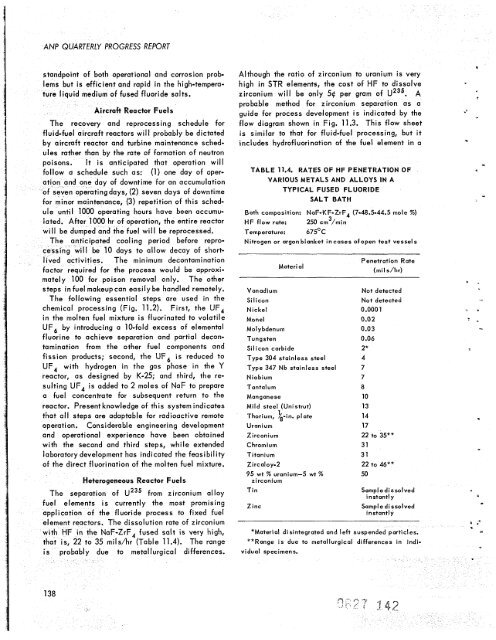
element reactors. The dissolution rate of zirconium<br />
with HF in <strong>the</strong> NaF-ZrF, fused salt is very high,<br />
that is, 22 to 35 milshr (Table 11.4). The range<br />
138<br />
probably due to metallurgical differences.<br />
Although <strong>the</strong> ratio of zirconium to uranium is very<br />
high in STR elements, <strong>the</strong> cost of HF to dissolve<br />
zirconium will be only 54 per gram of U235. A<br />
probable method for zirconium separation as a<br />
guide for process development is indicated by <strong>the</strong><br />
flow diagram shown in Fig. 11.3. This flow sheet<br />
is similar to that for fluid-fuel processing, but it<br />
includes hydrofluorination of <strong>the</strong> fuel element in a<br />
TABLE 11.4. RATES OF HF PENETRATION OF<br />
VARIOUS METALS AND ALLOYS IN A<br />
TYPICAL FUSED FLUORIDE<br />
SALT BATH<br />
Bath composition: NaF-KF-ZrF, (7-48.5-44.5 mole %)<br />
HF flow rate:<br />
3<br />
250 cm /min<br />
Temperature: 675'C<br />
Nitrogen or argon blanket incases ofopen test vessels<br />
Material<br />
Vanadium<br />
Si I icon<br />
Nickel<br />
Monel<br />
Molybdenum<br />
Tungsten<br />
Silicon carbide<br />
Type 304 stainless steel<br />
Type 347 Nb stainless steel<br />
Niobium<br />
Tantalum<br />
Manganese<br />
Mild steel (Unistrut)<br />
1 .<br />
Thorium, h-tn. plate<br />
Uranium<br />
Zirconium<br />
C hrom i um<br />
Titanium<br />
Zircaloy-2<br />
95 wt % uranium-5 wt %<br />
zircon i urn<br />
Tin<br />
Zinc<br />
Penetration Rate<br />
(mi I s /h r)<br />
Not detected<br />
Not detected<br />
0.0001<br />
0.02<br />
0.03<br />
0.06<br />
2*<br />
4<br />
7<br />
7<br />
8<br />
10<br />
13<br />
14<br />
17<br />
22 to 35**<br />
31<br />
31<br />
22 to 46**<br />
50<br />
Sampl e dissolved<br />
instantly<br />
Sample dissolved<br />
instantly<br />
*Material disintegrated and left suspended particles.<br />
**Range is due to metallurgical differences in indivi<br />
du a1 specimens.<br />
1<br />
*
![Review of Molten Salt Reactor Physics Calculations [Disc 2]](https://img.yumpu.com/21979492/1/190x247/review-of-molten-salt-reactor-physics-calculations-disc-2.jpg?quality=85)


