

ORNL-1816 - the Molten Salt Energy Technologies Web Site
ORNL-1816 - the Molten Salt Energy Technologies Web Site
ORNL-1816 - the Molten Salt Energy Technologies Web Site

You also want an ePaper? Increase the reach of your titles
YUMPU automatically turns print PDFs into web optimized ePapers that Google loves.
L<br />
.<br />
PERIOD ENDING DECEMBER 70, 7954<br />
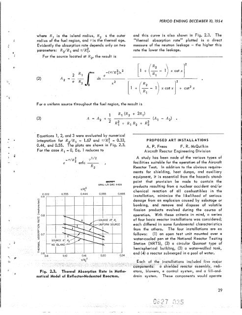
where R, is <strong>the</strong> island radius, R, s <strong>the</strong> outer and this curve is also shown in Fig. 2.3. The<br />
radius of <strong>the</strong> fuel region, and 7is <strong>the</strong> <strong>the</strong>rmal age. "<br />
<strong>the</strong>rmal absorption rate" plotted is CI direct<br />
Evidently <strong>the</strong> absorption rate depends only on two measure of <strong>the</strong> neutron leakage - <strong>the</strong> higher this<br />
parameters: R,/R and 7/R:. rate <strong>the</strong> lower <strong>the</strong> leakage.<br />
For <strong>the</strong> source located at R,, <strong>the</strong> result is<br />
2<br />
A =-<br />
2 T 7<br />
For a uniform source throughout <strong>the</strong> fuel region, <strong>the</strong> Eesult is<br />
(3)<br />
Equations 1, 2, and 3 were evaluated by numerical<br />
t integration for R2/Rl = 1.67 and 7/R: = 0.33,<br />
0.44, and 0.55. The plots are shown in Fig. 2.3.<br />
For <strong>the</strong> case R, = 0, Eq. 1 reduces to<br />
c<br />
-<br />
-T/Rf 71 /2<br />
e erfc - ,<br />
R2<br />
ertrrn<br />
<strong>ORNL</strong>-LR-DWG 4499<br />
0.222 0 222 0.333 0.444 0.555 0.666<br />
0.9 I , , I I I I I I<br />
(; /]<br />
2<br />
[l + - 1) x cot<br />
PROPOSED ART INSTALLATIONS<br />
A. P. Fraas F. R. McQuilkin<br />
Aircraft Reactor Eng i neer i ng Div i s ion<br />
A study has been made of <strong>the</strong> various types of<br />
facilities suitable for <strong>the</strong> operation of <strong>the</strong> Aircraft<br />
Reactor Test. In addition to <strong>the</strong> obvious require-<br />
ments for shielding, heat dumps, and auxiliary<br />
equipment, it is essential from <strong>the</strong> hazards stand-<br />
point that provision be made to contlclin <strong>the</strong><br />
products resulting from a nuclear accideni and/or<br />
chemical reaction of all combustibles in <strong>the</strong><br />
installation, minimize <strong>the</strong> likelihood of serious<br />
damage from an explosion caused by sabotage or<br />
bombing, and remove and dispose of volatile<br />
fission products evolved during <strong>the</strong> course of<br />
operation. With <strong>the</strong>se criteria in mind, CI series<br />
of four basic reactor installations was considered;<br />
each differed in some fundamental characieristics<br />
from <strong>the</strong> o<strong>the</strong>rs. The four installations are as<br />
follows: (1) an open test unit mounted over a<br />
water-cooled pan at <strong>the</strong> National Reactor Testing<br />
Station (NRTS), (2) a circular Quonset type of<br />
hemispherical building, (3) a water-walled tank,<br />
and (4) a reactor submerged in a pool of water.<br />
Fig. 2.3. Thermal Absorption Rate in Ma<strong>the</strong>- ators, blowers, a control system, and a .FiIl-and- Fill-andmatical<br />
Model of Reflector-Moderated Reactors. drain system. These components would operate<br />
..<br />
29
![Review of Molten Salt Reactor Physics Calculations [Disc 2]](https://img.yumpu.com/21979492/1/190x247/review-of-molten-salt-reactor-physics-calculations-disc-2.jpg?quality=85)


