

ORNL-1816 - the Molten Salt Energy Technologies Web Site
ORNL-1816 - the Molten Salt Energy Technologies Web Site
ORNL-1816 - the Molten Salt Energy Technologies Web Site

You also want an ePaper? Increase the reach of your titles
YUMPU automatically turns print PDFs into web optimized ePapers that Google loves.
1. CIRCULATING-FUEL AIRCRAFT REACTOR EXPERIMENT<br />
OPERATION OF THE AIRCRAFT REACTOR<br />
EXPERIMENT<br />
The Aircraft Reactor Exper iment was success-<br />
fully operated during <strong>the</strong> quarter. Uranium in <strong>the</strong><br />
form of molten Na,UF, was added to <strong>the</strong> barren<br />
carrier, NaZrF,, with which <strong>the</strong> fuel system was<br />
initially filled, to make <strong>the</strong> reactor critical. The<br />
fuel composition at initial criticality was 52.8-<br />
41.5-5.7 mole 5% (RaF-ZrF,-UF,), which has a<br />
melting point of 990°F, whereas <strong>the</strong> final fuel<br />
mixture (which included excess uranium) had a<br />
composition of 53.2-40.5-6.3 mole % (NaF-ZrF,-<br />
UF,) and a melting point of 1000°F.<br />
It was initially intended to remotely add <strong>the</strong><br />
concentrate to <strong>the</strong> fuel system from a large tank<br />
which contained all <strong>the</strong> concentrate, after first<br />
passing. it through an intermediate transfer tank.<br />
This system was discarded when temperature-<br />
control and continuous-weight-measuring instru-<br />
mentation on <strong>the</strong> transfer tank proved to be un-<br />
satisfactory. Instead, a less elaborate, but more<br />
direct, method of concentrate addition was em-<br />
ployed. This enrichment operation involved <strong>the</strong><br />
successive connection of numerous smal I concen-<br />
trate containers to an intermediate transfer pot,<br />
which was, in turn, connected to <strong>the</strong> fuel system<br />
by a line which injected <strong>the</strong> concentrate in <strong>the</strong><br />
pump above <strong>the</strong> liquid level. Each of <strong>the</strong> concen-<br />
trate containers was weighed before and after a<br />
transfer in order to determine <strong>the</strong> amount of<br />
uranium injected into <strong>the</strong> system. The concentrate<br />
was supplied in batches in cans containing from<br />
about 0.25 Ib of Na,UF, (for rod calibration) up<br />
to about 33 Ib (as was used during <strong>the</strong> first<br />
subcritical loading). In <strong>the</strong> enrichment operation<br />
<strong>the</strong> pump bowl served as a mixing chamber and<br />
uniformly distributed <strong>the</strong> concentrate into <strong>the</strong><br />
circulating stream. (For details of <strong>the</strong> loading<br />
operation see -foliowing subsection on “Loading<br />
of <strong>the</strong> ARE.”)<br />
The first concentrate addition was made on<br />
October 30, but <strong>the</strong> reactor did not become critical<br />
until three days later (3:45 PM, November 3).<br />
Most of <strong>the</strong> intervening time was spent in clearing<br />
<strong>the</strong> end of <strong>the</strong> transfer line at <strong>the</strong> pump, which,<br />
because of limitations inherent to only this par-<br />
E. S. Bettis J. L. Meem<br />
Aircraft Reactor Engineering Division<br />
ticular design, was difficult to heat and even more<br />
difficult to service.<br />
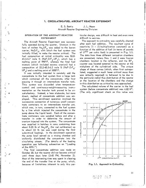
The approach to criticality was carefully charted<br />
after each fuel addition. The resultant curve of<br />
reactivity [I - (l/multiplication constant)] as a<br />
function of <strong>the</strong> addition of fuel (in terms of pounds<br />
of U235 per cubic foot) is presented in Fig. 1.1.<br />
The data from three different ionization chambers<br />
are presented; meters Nos. 1 and 2 were fission<br />
chambers located in <strong>the</strong> reflector, and <strong>the</strong> BF,<br />
counter was located external to <strong>the</strong> reactor at <strong>the</strong><br />
mid-plane of <strong>the</strong> cylindrical side. The unique<br />
shape of <strong>the</strong>se curves (which, when first (extrapo-<br />
lated, suggested a much lower critical mass than<br />
was actually required) is believed to be due to<br />
<strong>the</strong> particular radial flux distribution of <strong>the</strong> reactor<br />
at <strong>the</strong> location of <strong>the</strong> chambers and <strong>the</strong> change<br />
in this distribution as criticality was approached.<br />
The calculated volume of <strong>the</strong> carrier in <strong>the</strong> fuel<br />
system (before concentrate addition) was 4.82 ft3.<br />
(The only significant check on this value was<br />
1.0<br />
0.9<br />
0.8<br />
z 0.7<br />
0<br />
+<br />
0<br />
2 0.6<br />
-<br />
+<br />
-I 3<br />
I<br />
1 0.5<br />
-.<br />
0.4<br />
0.3<br />
02<br />
0 4 8 i2 16 20 24 28<br />
U235 CONCENTRATION (lb/ft3)<br />
Fig. 1.1. Approach to Criticality.
![Review of Molten Salt Reactor Physics Calculations [Disc 2]](https://img.yumpu.com/21979492/1/190x247/review-of-molten-salt-reactor-physics-calculations-disc-2.jpg?quality=85)


