

ORNL-1816 - the Molten Salt Energy Technologies Web Site
ORNL-1816 - the Molten Salt Energy Technologies Web Site
ORNL-1816 - the Molten Salt Energy Technologies Web Site

You also want an ePaper? Increase the reach of your titles
YUMPU automatically turns print PDFs into web optimized ePapers that Google loves.
1<br />
ANP QUARTERLY PROGRESS REPORT<br />
19.1<br />
39.0 pg/cm2<br />
tBERYLLIVM INSERT<br />
LENGTH - 3.75 in<br />
ID-04301n<br />
UNCLASSIFIED<br />
<strong>ORNL</strong>-LR-DWG 4650<br />
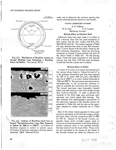
ution of Beryllium Around an<br />
oop Containing a Beryllium<br />
m. Test period, 270 hr.<br />
g. 6.2. Surfaces of Beryllium Insert from an<br />
nconel Thermal-Convection Loop After Exposure<br />
to Sodium for 1000 hr at 13OO0F. (u) Surface of<br />
beryllium exposed to sodium in annular space.<br />
(b) Surface of beryllium exposed to flowing sodium.<br />
OOX. Reduced 37.5%.<br />
under way to determine <strong>the</strong> minimum spacing that<br />
can be tolerated between beryllium and Inconel.<br />
STATIC CORROSION STUDIES<br />
E. E. Hoffman<br />
W. H. Cook C. F. Leitten<br />
Metallurgy Division<br />
Brazing Alloys on Stainless Steel<br />
Additional tests have been made in an effort to<br />
find a brazing alloy that has good resistance to<br />
both sodium and <strong>the</strong> fuel mixture NaF-ZrF,-UF,<br />
(53.5-40-6.5 mole %). The results reported in Table<br />
6.5 were obtained from tests of type 304 stainless<br />
steel T-joints brazed with <strong>the</strong> alloys listed by <strong>the</strong><br />
Wall Colmonoy Corporation. Tests are also being<br />
conducted on Inconel T-joints brazed with each of<br />
<strong>the</strong> alloys listed in Table 6.5. All <strong>the</strong> brazing<br />
alloys listed had good resistance to <strong>the</strong> fluoride<br />
mixture, but only alloy C-29 had good resistance<br />
to both <strong>the</strong> fluoride mixture and to sodium.<br />
Brazing Alloys on Nickel<br />
A series of T-ioints of A-nickel were brazed with<br />
<strong>the</strong> various alloys listed in Tables 6.6 and 6.7 in<br />
a dry hydrogen atmosphere and were <strong>the</strong>n exposed<br />
for 100 hr to static NaF-ZrF,-UF, (53.5-40-6.5<br />
mole %) at 1500°F or to static sodium hydroxide at<br />
1100 and 15OOOF. The specimens were examined me-<br />
tallographically in <strong>the</strong> as-received condition in<br />
order to evaluate <strong>the</strong> inclusions and <strong>the</strong> porosity.<br />
The brazed specimens were thoroughly cleaned<br />
before and after testing so that Val id weight change<br />
data could be obtained. In order to prevent <strong>the</strong><br />
rounding of <strong>the</strong> fillet edge upon polishing, each<br />
specimen was nickel plated after testing. The<br />
data obtained from metallographic examination of<br />
<strong>the</strong> specimens exposed to <strong>the</strong> fluoride mixture are<br />
presented in Table 6.6, and <strong>the</strong> data on <strong>the</strong> speci-<br />
mens exposed to sodium hydroxide are in Table<br />
6.7.<br />
Most of <strong>the</strong> alloys tested appeared to have good<br />
corrosion resistance to <strong>the</strong> fluoride mixture, except<br />
<strong>the</strong> braze alloy with <strong>the</strong> composition 69% Ni-20%<br />
Cr-ll% Si. Several of <strong>the</strong> brazed T-ioints, especially<br />
those which included copper, gold, or<br />
silicon as an alloying element in <strong>the</strong> braze material,<br />
showed numerous voids in <strong>the</strong> interface between<br />
<strong>the</strong> base material and <strong>the</strong> braze fillet. These voids<br />
are not considered to be caused by <strong>the</strong> attack of<br />
<strong>the</strong> fluoride mixture but ra<strong>the</strong>r by diffusion of a<br />
5 "<br />
3<br />
I<br />
-
![Review of Molten Salt Reactor Physics Calculations [Disc 2]](https://img.yumpu.com/21979492/1/190x247/review-of-molten-salt-reactor-physics-calculations-disc-2.jpg?quality=85)


