special - Alu-web.de
special - Alu-web.de
special - Alu-web.de

You also want an ePaper? Increase the reach of your titles
YUMPU automatically turns print PDFs into web optimized ePapers that Google loves.
ECo N o M i CS<br />
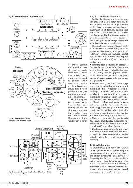
Fig. 3: Layout of digestion / evaporation areas<br />
Fig. 4: Layout of residue settling,<br />
washing and lime areas<br />
Fig. 5: Layout of hydrate classification / filtration<br />
and oxalate removal areas<br />
ed process technologies<br />
(digestion, impurity<br />
removal, equipment<br />
types – filters,<br />
heat exchangers, etc.),<br />
plant location specifics<br />
(rainfall – water<br />
balance, legal requirements,<br />
soil conditions,<br />
gravity flow between<br />
precipitators, etc.), and<br />
operating and maintenance<br />
philosophies.<br />
The following layout<br />
consi<strong>de</strong>rations are<br />
based on the selected<br />
refining process, <strong>de</strong>sign,<br />
equipment sparing,<br />
operating parameters<br />
and equipment.<br />
However most of these<br />
would (fully or partly)<br />
apply also if other choices are ma<strong>de</strong>.<br />
• Position the digestion and liquor evaporation<br />
areas next to each other (refer Fig. 3).<br />
The causticiser feed heat exchanger is located<br />
in the digestion / evaporation area because<br />
evaporation export steam and digestion flash<br />
con<strong>de</strong>nsate is used to heat the CCDwasher<br />
overflow to causticisation. Attention should be<br />
given to maintain the free caustic concentration<br />
in the spent liquor through evaporation<br />
at the hot end within acceptable levels.<br />
• Place the bauxite residue settler and washers<br />
in a horseshoe shape for easy access to<br />
washer overflow standpipes and pumps, etc.<br />
(refer Fig. 4). Lime related areas are positioned<br />
next to each other (similar operating and<br />
maintenance requirements) and close to the<br />
washer train.<br />
• Place the filters for hydrate to calcination,<br />
fine seed for precipitation and oxalate removal,<br />
as well as the cyclone classification areas<br />
in one building (similar equipment, operating<br />
and maintenance procedures, spare parts,<br />
sharing of common spare tanks and pumps,<br />
etc.) (refer Fig. 5).<br />
• Position security filtration related equipment<br />
close to each other for operating and<br />
maintenance efficiency reasons; the heat interchange,<br />
precipitation and interstage cooling<br />
close to each other as these have many<br />
interactions (minimising liquor / slurry pipeline<br />
distances); and the main steam consumers<br />
(digestion and evaporation) and the steam<br />
and power plant close to each other to minimise<br />
energy losses; and place if feasible the<br />
bauxite crushing, grinding and pre<strong>de</strong>silication<br />
areas close to each other and to the digestion<br />
area to minimise slurry pipeline distances.<br />
• Construct in the centre of the plant a facility<br />
accommodating the plant control room (including<br />
control of the steam and power plant),<br />
operations office and plant laboratory.<br />
• Create good crane access to all major equipment<br />
from 15 m wi<strong>de</strong> plant roads, and if economically<br />
justifiable consi<strong>de</strong>r pipe trenches<br />
instead of piperacks for road crossings (ease<br />
of access).<br />
4.4 Overall plant layout<br />
An overall process plant layout for a 400,000<br />
tpy DCS plant is shown in Fig. 6, showing that<br />
the new approach leads to a compact, simple<br />
and efficient layout with a small Bayer loop,<br />
illustrating that the goal to tailor the <strong>de</strong>sign<br />
to the equipment and infrastructure requirements<br />
of the specified production capacity is<br />
achievable: most of the infrastructure is integrated<br />
in the process areas and only limited<br />
infrastructure is required outsi<strong>de</strong> those. ➝<br />
ALUMINIUM · 7-8/2013 27