

Hardware Manual - RTD Embedded Technologies, Inc.
Hardware Manual - RTD Embedded Technologies, Inc.
Hardware Manual - RTD Embedded Technologies, Inc.

You also want an ePaper? Increase the reach of your titles
YUMPU automatically turns print PDFs into web optimized ePapers that Google loves.
8254 Timer/Counters<br />
Two 8254 programmable interval timers provide six (three each) 16-bit, 8 MHz timer/counters to support a wide<br />
range of board operations and user timing and counting functions.<br />
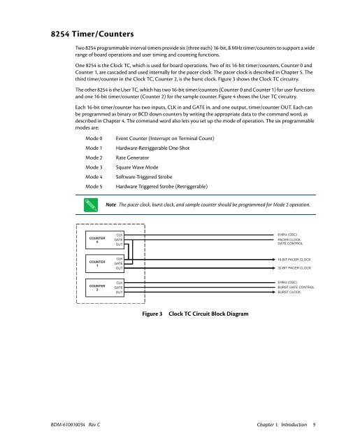
One 8254 is the Clock TC, which is used for board operations. Two of its 16-bit timer/counters, Counter 0 and<br />
Counter 1, are cascaded and used internally for the pacer clock. The pacer clock is described in Chapter 5. The<br />
third timer/counter in the Clock TC, Counter 2, is the burst clock. Figure 3 shows the Clock TC circuitry.<br />
The other 8254 is the User TC, which has two 16-bit timer/counters (Counter 0 and Counter 1) for user functions<br />
and one 16-bit timer/counter (Counter 2) for the sample counter. Figure 4 shows the User TC circuitry.<br />
Each 16-bit timer/counter has two inputs, CLK in and GATE in, and one output, timer/counter OUT. Each can<br />
be programmed as binary or BCD down counters by writing the appropriate data to the command word, as<br />
described in Chapter 4. The command word also lets you set up the mode of operation. The six programmable<br />
modes are:<br />
Mode 0<br />
Mode 1<br />
Mode 2<br />
Mode 3<br />
Mode 4<br />
Mode 5<br />
Event Counter (Interrupt on Terminal Count)<br />
<strong>Hardware</strong>-Retriggerable One-Shot<br />
Rate Generator<br />
Square Wave Mode<br />
Software-Triggered Strobe<br />
<strong>Hardware</strong> Triggered Strobe (Retriggerable)<br />
Note The pacer clock, burst clock, and sample counter should be programmed for Mode 2 operation.<br />
COUNTER<br />
0<br />
CLK<br />
GATE<br />
OUT<br />
8 MHz (OSC)<br />
PACER CLOCK<br />
GATE CONTROL<br />
COUNTER<br />
1<br />
CLK<br />
GATE<br />
OUT<br />
16-BIT PACER CLOCK<br />
32-BIT PACER CLOCK<br />
COUNTER<br />
2<br />
CLK<br />
GATE<br />
OUT<br />
8 MHz (OSC)<br />
BURST GATE CONTROL<br />
BURST CLOCK<br />
Figure 3<br />
Clock TC Circuit Block Diagram<br />
BDM-610010034 Rev C Chapter 1: Introduction 9


