

Hardware Manual - RTD Embedded Technologies, Inc.
Hardware Manual - RTD Embedded Technologies, Inc.
Hardware Manual - RTD Embedded Technologies, Inc.

You also want an ePaper? Increase the reach of your titles
YUMPU automatically turns print PDFs into web optimized ePapers that Google loves.
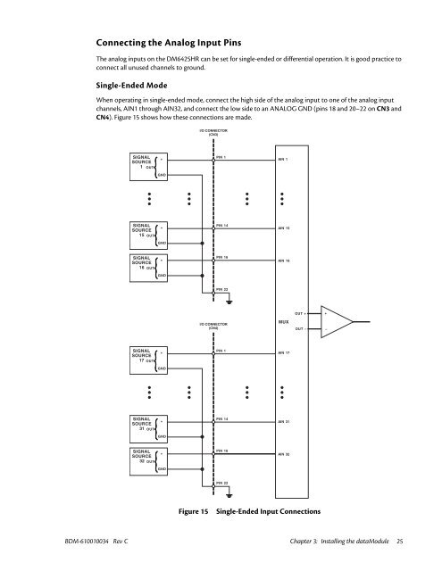
Connecting the Analog Input Pins<br />
The analog inputs on the DM6425HR can be set for single-ended or differential operation. It is good practice to<br />
connect all unused channels to ground.<br />
Single-Ended Mode<br />
When operating in single-ended mode, connect the high side of the analog input to one of the analog input<br />
channels, AIN1 through AIN32, and connect the low side to an ANALOG GND (pins 18 and 20–22 on CN3 and<br />
CN4). Figure 15 shows how these connections are made.<br />
I/O CONNECTOR<br />
(CN3)<br />
SIGNAL<br />
SOURCE<br />
1 OUT<br />
+<br />
PIN 1<br />
AIN 1<br />
GND<br />
SIGNAL<br />
SOURCE<br />
15 OUT<br />
+<br />
PIN 14<br />
AIN 15<br />
GND<br />
SIGNAL<br />
SOURCE<br />
16 OUT<br />
+<br />
PIN 16<br />
AIN 16<br />
GND<br />
PIN 22<br />
OUT +<br />
+<br />
I/O CONNECTOR<br />
(CN4)<br />
MUX<br />
OUT –<br />
–<br />
SIGNAL<br />
SOURCE<br />
17 OUT<br />
+<br />
PIN 1<br />
AIN 17<br />
GND<br />
SIGNAL<br />
SOURCE<br />
31 OUT<br />
+<br />
PIN 14<br />
AIN 31<br />
GND<br />
SIGNAL<br />
SOURCE<br />
32 OUT<br />
+<br />
PIN 16<br />
AIN 32<br />
GND<br />
PIN 22<br />
Figure 15<br />
Single-Ended Input Connections<br />
BDM-610010034 Rev C Chapter 3: Installing the dataModule 25


