Hardware Manual - RTD Embedded Technologies, Inc.
Hardware Manual - RTD Embedded Technologies, Inc.
Hardware Manual - RTD Embedded Technologies, Inc.
You also want an ePaper? Increase the reach of your titles
YUMPU automatically turns print PDFs into web optimized ePapers that Google loves.
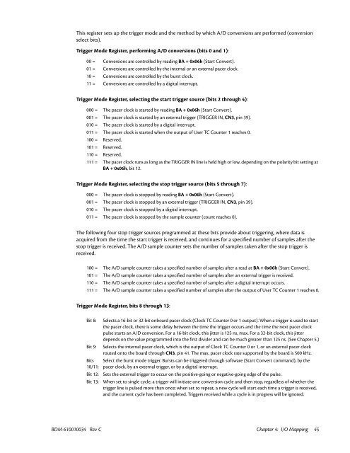
This register sets up the trigger mode and the method by which A/D conversions are performed (conversion<br />
select bits).<br />
Trigger Mode Register, performing A/D conversions (bits 0 and 1):<br />
00 = Conversions are controlled by reading BA + 0x06h (Start Convert).<br />
01 = Conversions are controlled by the internal or an external pacer clock.<br />
10 = Conversions are controlled by the burst clock.<br />
11 = Conversions are controlled by a digital interrupt.<br />
Trigger Mode Register, selecting the start trigger source (bits 2 through 4):<br />
000 = The pacer clock is started by reading BA + 0x06h (Start Convert).<br />
001 = The pacer clock is started by an external trigger (TRIGGER IN, CN3, pin 39).<br />
010 = The pacer clock is started by a digital interrupt.<br />
011 = The pacer clock is started when the output of User TC Counter 1 reaches 0.<br />
100 = Reserved.<br />
101 = Reserved.<br />
110 = Reserved.<br />
111 = The pacer clock runs as long as the TRIGGER IN line is held high or low, depending on the polarity bit setting at<br />
BA + 0x06h, bit 12.<br />
Trigger Mode Register, selecting the stop trigger source (bits 5 through 7):<br />
000 = The pacer clock is stopped by reading BA + 0x06h (Start Convert).<br />
001 = The pacer clock is stopped by an external trigger (TRIGGER IN, CN3, pin 39).<br />
010 = The pacer clock is stopped by a digital interrupt.<br />
011 = The pacer clock is stopped by the sample counter (count reaches 0).<br />
The following four stop trigger sources programmed at these bits provide about triggering, where data is<br />
acquired from the time the start trigger is received, and continues for a specified number of samples after the<br />
stop trigger is received. The A/D sample counter sets the number of samples taken after the stop trigger is<br />
received.<br />
100 = The A/D sample counter takes a specified number of samples after a read at BA + 0x06h (Start Convert).<br />
101 = The A/D sample counter takes a specified number of samples after an external trigger is received.<br />
110 = The A/D sample counter takes a specified number of samples after a digital interrupt occurs.<br />
111 = The A/D sample counter takes a specified number of samples after the output of User TC Counter 1 reaches 0.<br />
Trigger Mode Register, bits 8 through 13:<br />
Bit 8:<br />
Bit 9:<br />
Bits<br />
10/11:<br />
Bit 12:<br />
Bit 13:<br />
Selects a 16-bit or 32-bit onboard pacer clock (Clock TC Counter 0 or 1 output). When a trigger is used to start<br />
the pacer clock, there is some delay between the time the trigger occurs and the time the next pacer clock<br />
pulse starts an A/D conversion. For a 16-bit clock, this jitter is 125 ns, max. For a 32-bit clock, this jitter<br />
depends on the value programmed into the first divider and can be much greater than 125 ns. (See Chapter 5.)<br />
Selects the internal pacer clock, which is the output of Clock TC Counter 0 or 1, or an external pacer clock<br />
routed onto the board through CN3, pin 41. The max. pacer clock rate supported by the board is 500 kHz.<br />
Select the burst mode trigger. Bursts can be triggered through software (Start Convert command), by the<br />
pacer clock, by an external trigger, or by a digital interrupt.<br />
Sets the external trigger to occur on the positive-going or negative-going edge of the pulse.<br />
When set to single cycle, a trigger will initiate one conversion cycle and then stop, regardless of whether the<br />
trigger line is pulsed more than once; when set to repeat, a new cycle will start each time a trigger is received,<br />
and the current cycle has been completed. Triggers received while a cycle is in progress will be ignored.<br />
BDM-610010034 Rev C Chapter 4: I/O Mapping 45


